Hardware Design Specification
ASD-B-16-0247 Rev1.3
Page 24 of 105
September 8, 2017
RTK00V2XRC7746SFS
3.7
Mini PCI Express Interface
3.7.1
Specifications
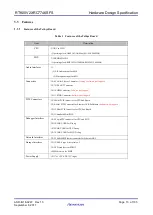
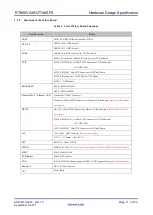
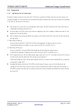
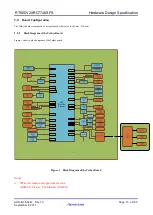
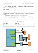
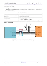
The Tethys board incorporates four mini PCIE interface manufactured by TE. One Mini-PCI Express CN(CN9) is connected to
SDHI0, GPIO, SCIF0 and the HSCIF0 of the R-Car W2H, another Mini-PCI Express CN(CN12) is connected to SDHI2, GPIO,
SCIF3 and the HSCIF2 of the R-Car W2H, and the third Mini-PCI Express CN(CN8) is connected to the Ethernet MAC/Ethernet
AVB, GPIO and the HSCIF1 of the R-Car W2H, The fourth Mini-PCI Express CN(CN11) acts as a standard Mini-PCI Express
signal connector and transmits the standard Mini-PCI Express signals. There are also USB 2.0 signals and 1pps signal connected to
the mini PCIE connectors.
3.7.2
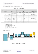
The Mini PCIE connector signal configuration are shown as below:
3.7.2.1
CN9 of figure 7 signal assignments are shown as below:
Pin NO.
Signal
I/O
Remark
Pin NO.
Signal
I/O
Remark
1
C2X0_DCMODE
O
GPIO
2
D3.3V
PO
Power
3
N.C.
-
4
GND
-
Power
5
PCIE_5.0V
PO
Power
6
PCIE_5.0V
PO
Power
7
C2X0_RESETB
O
GPIO
8
GPS_1PPS/
C2X0_GPIO_B3
I/O
GPS 1PPS
output
or GPIO
9
GND
-
Power
10
C2X0_GPIO_B2
I/O
GPIO
11
RX0_D/
C2X_RXD
I
UART from CPU
or USB2UART
12
C2X0_GPIO_B1
I/O
GPIO
13
TX0_D/
C2X_TXD
O
UART from CPU
or USB2UART
14
C2X0_GPIO_B0
I/O
GPIO
15
GND
-
Power
16
C2X0_STATE
I
C2X state
17
N.C.
-
18
GND
-
Power
19
N.C.
-
20
C2X0_GPIO_A6
I/O
GPIO
21
GND
-
Power
22
C2X0_GPIO_A5
I/O
GPIO
23
HRX0_B
I
UART from CPU
24
PCIE_5.0V
PO
Power
25
HTX0_B
O
UART from CPU
26
GND
-
Power
27
GND
-
Power
28
PCIE_5.0V
PO
Power
29
GND
-
Power
30
C2X0_GPIO_A4
I/O
GPIO
31
MD10/HCTS0#
I/O
UART from CPU
32
C2X0_GPIO_A3
I/O
GPIO
33
MD11/HRTS0#
I/O
UART from CPU
34
GND
-
Power
35
GND
-
Power
36
N.C
-
37
SD0_CLK
O
SD0 clock
38
N.C
-
39
SD0_WP
I
SD0 write protect
40
GND
-
Power
41
SD0_CD
I
SD0 card detect
42
C2X0_GPIO_A2
I/O
GPIO

