


Hardware Design Specification
ASD-B-16-0247 Rev1.3
Page 41 of 105
September 8, 2017
RTK00V2XRC7746SFS
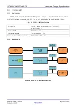
3.15
LEDs and Switches
3.15.1
Specifications
The Tethys board incorporates four bits of tactile switches, and four bits of LEDs (eight LEDS for 4 GPIO place both top and
bottom side of the PCB) for debugging and status indication. They are connected to the GPIO pins of the R-Car W2H. Besides, there
are two LEDS control by the GPS 1PPS signal to indicate the GPS work status. The LED controlled by R-Car W2H port and GPS
1PPS signal correspondingly is shown as the table below,
LED
R-Car W2H
PORT
Color
D3&D4
GP5_4
Green
D5&D6
GP5_5
Green
D7&D8
GP5_6
Green
D9&D10
GP5_7
Green
LED
Signal
Color
D11&D12
GPS_1PPS
Green
The tactile switch controlled by R-Car W2H or MCU port correspondingly is shown as the table below,
Tact SW
R-Car W2H or MCU PORT
SW13
GP5_0
SW14
GP5_1
SW15
GP5_2
SW16
GP5_3
SW4
MCU reset
There are other Switches are listed as below:
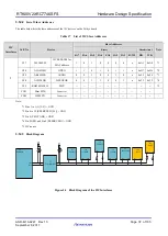
Table 19 DIP Switches default setting is as below table
DIP Switch
Description
Function
Default setting
ON(Short)
OFF(Open)
SW1
eMMC interface
and RL JTAG
Select switch
eMMC
JTAG
SW1: 1-16 short
SW1: 1-16 open
○
SW1: 2-15 short
SW1: 2-15 open
○
SW1: 3-14 short
SW1: 3-14 open
○
SW1: 4-13 short
SW1: 4-13 open
○
SW1: 5-12 short
SW1: 5-12 open
○
SW1: 6-11 short
SW1: 6-11 open
○
SW1: 7-10 open
SW1: 7-10 short
○
SW1: 8-9 open SW1: 8-9 short
○


