6.6.4
Installation of the connection box
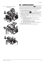
The connection box contains the standard PCB CB-01 and the optional
PCB(s) for the external connections. The connection box is included with
the delivery of the boiler as standard. Use the connection cables supplied
to connect the connection box to the control unit. Proceed as follows:
1. Unscrew the retaining screw on the front of the housing.
2. Open the front flap of the housing.
3. Connect the connection cable X035 to the connector from the boiler.
4. Connect the connection cable X018 to the connector from the boiler.
5. Place the connection box for the mounting clips in the housing.
6. Carefully push the connection box downwards over the mounting clips
and tighten the two screws.
7. Now connect the desired external controllers to the other connectors.
Proceed as follows:
7.1. Unscrew the retaining screw on the cable duct cover.
7.2. Remove the cable duct cover.
7.3. Route the cable of the external controllers or the sensor
through the cable duct.
7.4. Lay the cable under the strain relief clip.
7.5. Turn the strain relief clip firmly into place.
7.6. Replace the cable duct cover and tighten the retaining screw.
8. Close the front flap of the housing.
9. Retighten the retaining screw on the front of the housing.
Fig.35
Installing and connecting the
connection box
AD-0001176-01
8
90º
9
7.1
7.2
7.6
7.3
7.4
7.5
90º
1
2
6
6
5
4
3
5
X035
X018
6 Installation
7665063 - v.05 - 18102018
39
Содержание Gas 220 Ace 160
Страница 88: ...14 Appendix 88 7665063 v 05 18102018 ...
Страница 89: ...14 Appendix 7665063 v 05 18102018 89 ...
Страница 90: ...14 Appendix 90 7665063 v 05 18102018 ...

