Regin PDTX C Series Скачать руководство пользователя страница 2

Installation

The transmitter comes with one cable gland mounted and two loose. If
more than one cable is used, the other cable glands must be assembled to
the housing. Screw in the cable gland until the plastic knockout in the
housing snaps. Make sure to remove the plastic knockout completely.
Secure the cable gland. See

Figure 1

.

Figure 1 Installing the cable glands

1. Mount the transmitter horizontally or vertically on a stable,

vibration-free surface. If the unit is installed in a humid
environment, install it vertically with the cable gland edge of the unit
pointing down to allow moisture to escape.

2. Refer to the graphics below for wiring. Connect the communication

cable to terminals 3(A) and 4(B). Use the leftmost cable gland for
supply voltage and communication.

3. Power up the unit. Set the desired communication settings in the

menu (see

Settings

). Note that the transmitter uses the default

Modbus address = 1.

4. Refer to the Presigo PDTX…-C variable list for information on how

to access transmitter data.

5. Let the unit warm up for 10 minutes, then perform a zero-set

calibration by pressing the push-button (see

Handling

).

6. Connect plastic tubes from the ventilation duct to the pressure

inlets.

The two leftmost inlets are connected to sensor 1 and the other two
to sensor 2. The inlet marked with '+' should be used to connect the
tube with the highest pressure and the inlet marked with '-' to the
one with the lowest pressure.

N

Noottee!! A straight cut off nipple must be used for mounting in the ventila-

tion duct.

For optimal measuring results, measuring points with turbulent air flow
should be avoided. Preferably, measuring should be performed at a
distance of 2 duct diameters before bends and branching and at 6 duct
diameters after bends and branching.

Wiring

Terminal

Name

Description

1

24 V (G) +

Power supply 24 V AC/DC (Positive)

2

24 V (G0) -

Power supply 24 V AC/DC (Negative/
Ground)

3

RS485 - A

Communication A (-)

4

RS485 - B

Communication B (+)

5

UO1

Universal output 1

6

24 V (G) +

Internally connected to Terminal 1

7

GND

Internally connected to Terminal 2

8

UO2

Universal output 2

9

UI1

Universal input 1

10

GND

Internally connected to Terminal 2

11

UI2

Universal input 2

Use a shielded, twisted pair cable for RS485 communication. At high
risks of interference, a 120 Ω terminating resistor should be mounted at
each end of the communications circuit.
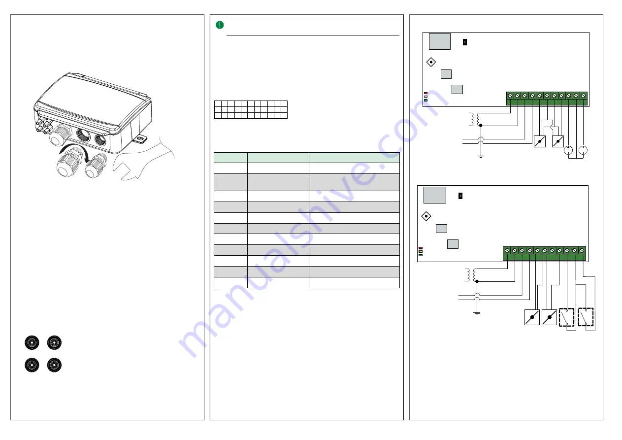
Wiring examples

Figure 2 UIx as 0…10 V input and UOx as 0…10 V output

Figure 3 UIx as digital input and UOx as digital output

+

1

2

-

Ɵ Ɵ Ɵ Ɵ Ɵ Ɵ Ɵ Ɵ Ɵ Ɵ Ɵ

1 2 3 4 5 6 7 8 9 10 11

□ □ □ □ □ □ □ □ □ □ □

2

4

V

(G

) +

2

4

V

(G

0

) -

R

S4

8

5

-A

R

S4

8

5

-B

U

O

1

2

4

V

(G

) +

G

N

D

U

O

2

U

I1

G

N

D

U

I2

24V AC/DC

1   2   3   4   5   6   7   8   9  10 11

Sensor 1

Sensor 2 (when available)

0...10 V

+

-

GND

Status LEDs

RS485

Modbus

Push-button

Display

Joystick

0...10 V

A
B

Optional

1   2   3   4   5   6   7   8   9  10 11

Sensor 1

Sensor 2 (when available)

Status LEDs

Push-button

Display

Joystick

1   2   3   4   5   6   7   8   9  10 11

24V AC/DC

+

-

RS485

Modbus

Digital
Potential-free

A
B

Digital

Presigo

2 (18)

Содержание PDTX C Series

Страница 1: ...inH2O Working range flow 0 65000 m3 h factory setting 0 31000 l s 0 65000 Ft3 min Cable glands 2 x M20 cable diameter 5 12 mm 1 x M16 cable diameter 3 5 10 mm Max overvoltage 18 V on any terminal not...

Страница 2: ...st pressure and the inlet marked with to the one with the lowest pressure N No ot te e A straight cut off nipple must be used for mounting in the ventila tion duct For optimal measuring results measur...

Страница 3: ...2 UI2 u UI Value in 0 10 V mode u 1 UI1 u 2 UI2 t UI Value in temperature mode C t 1 UI1 t 2 UI2 L UO Value in digital mode L 1 UO1 L 2 UO2 U UO Value in 0 10 V mode U 1 UO1 U 2 UO2 Two digits can be...

Страница 4: ...ntrols com O Ob bs se er rv ve er ra a L s och f rst instruktionen innan du anv nder produkten O Ob bs se er rv ve er ra a Se till att installationen uppfyller lokala s kerhetsbest mmelser O Ob bs se...

Страница 5: ...till plint 3 A och 4 B Anv nd v nster kabelgenomf ring f r matningssp nning och kommunikation 3 Sp nningss tt enheten G r de kommunikationsinst llningar som nskas i menyn se Inst llningar Notera att t...

Страница 6: ...joysticken till v nster f r att avf rda ndringarna 7 F r joysticken till v nster f r att terg till f reg ende meny N No ot te er ra a Den senast gjorda inst llningen i transmittern g ller alltid oavse...

Страница 7: ...n ut f rs L t enheten v rma upp i 10 minuter innan ett f rs k till nollpunktska librering g rs Fabriks terst llning Ett l ngt tryck p tryckknappen mer n 10 sekunder utf r en fabriks terst llning av an...

Страница 8: ...e 24 V AC oder DC 2 A kontinuierlich Ausgang Spannungsversorgung Max 2 A gesamt UO1 UO2 Kommunikation ber Datenschnittstelle Kommunikationsschnitt stellen 1 Schnittstellentyp RS485 Unterst tzte Protok...

Страница 9: ...rbunden mit Klemme 1 7 GND Intern verbunden mit Klemme 2 8 UO2 Universalausgang 2 Klemme Name Beschreibung 9 UI1 Universaleingang 1 10 GND Intern verbunden mit Klemme 2 11 UI2 Universaleingang 2 Verwe...

Страница 10: ...den mehrere aufeinanderfolgende Anzeigen verwendet um einen l ngeren Wert darzustellen Beispiel Ein Druckwert von 2350 Pa am F hler 1 wird mit drei Anzeigen dargestellt d h 1 P 1 2 23 3 50 Die Ma einh...

Страница 11: ...tallation est conforme aux normes de s curit locales A At tt te en nt tiio on n Avant de proc der l installation ou la maintenance de l ap pareil il convient de couper l alimentation lectrique Les op...

Страница 12: ...et 4 B Utiliser l entr e la plus gauche pour l alimentation et la communication 3 Mettre le r gulateur sous tension R gler les param tres de communication partir du menu voir R glages Note Adresse Mod...

Страница 13: ...par un mouvement vers la gauche 7 Manette vers la gauche pour un retour l cran pr c dent N NB B La derni re configuration entr e dans le transmetteur est toujours valide ind pendamment de la configura...

Страница 14: ...ression R initialisation Un appui long sur le bouton poussoir plus de 10 secondes lance la r initialisation aux param tres usine Tableau 4 indique les param tres restaur s Tableau 4 R glages usine Des...

Страница 15: ...Lunghezza del cavo Max 100 m Modelli Articolo Numero di sensori Max pressione di sovraccarico kPa Campo di misura pressione Pa PDTX12 C 1 25 0 1250 PDTX25 C 1 50 0 2500 PDTX75 C 1 120 0 7500 PDTX12 2...

Страница 16: ...ualizzate e modificate tramite il sistema di menu o tramite Modbus Tutte le altre impostazioni sono accessibili e modificabili tramite Modbus Il joystick viene utilizzato per spostarsi all interno del...

Страница 17: ...bps Tabella 3 Impostazioni nel sottomenu C Impostazioni Modbus Descrizione n1 8 byte 1 bit di stop nessuna parit impo stazione di fabbrica n2 8 byte 2 bit di stop nessuna parit E1 8 byte 1 bit di sto...

Страница 18: ...u www industrietechnik it Documentazione La documentazione pu essere scaricata da www industrietechnik it Contatti AB Industrietechnik SRL Via Julius Durst Str 50 I 39042 Bressanone BZ Tel 39047283062...

Отзывы: