16
b) Assembly of the Rotors
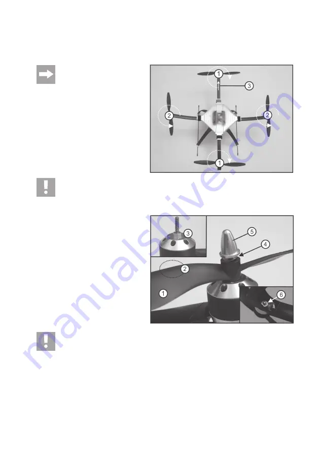
The rotating direction of the rotors can be seen in the adjacent figure (bird’s eye view). The arrow on the radial arm is
to be used as the indication for the direction of the model and is deemed to be “front”.
Attention!
As the motors are pre-assembled, the
rotating direction of the rotors on the
basis of the flight direction should be
carefully observed (figure 3)!
The rotors in the centre line (1) turn clockwise (right
rotating) and must be marked with the inscription
“RIGHT”.
The rotors on the cross axis (2) turn anticlockwise
(left rotating) and must be marked with the inscrip-
tion “LEFT”.
The arrow at the radial arm (3) indicates “front”.
Attention!
If the rotors are not installed as described, the programmed rotating directions will no longer be in line with
the rotating directions of the rotors. The QuadroCopter is therefore no longer able to fly and can no longer
be operated! Loss of guarantee/warranty!
Rotors and motor shafts are provided with a hex-
agonal bolt (3).
Place the rotors (1) on the motor shafts (3) so that
they lock into place in the hexagonal bolt. Observe
the indication of “RIGHT” and “LEFT” on the rotors
(2).
Now insert one of the provided spring washers (4)
at a time between the rotor and rotor tip (5), as
otherwise the rotors may become loose during
flight.
Screw the rotor tops to the motor shafts manually.
Attention!
Tightening the screws too much can damage the motors. The shafts may tear or be pulled from the
bearings. The motors operate sluggishly, which may have a negative effect on the flight characteristics.
Therefore, please verify that all of the rotors can turn easily after tightening the rotors. The snap ring shown
in figure 4, item 6, on the underside of the motors must be able to move and must not jam.
Please ensure before each operation that the rotors are firmly screwed in place on the motors. It is recom-
mended that you are careful when handling work tools.
Figure 3
Figure 4
Содержание 650
Страница 1: ... QuadroCopter 650 V2 ARF MEMS Item no 27 51 00 Version 10 11 Operating Instructions ...
Страница 30: ...30 l Possible Flight Modes Mode Throttle Yaw Pitch Roll 1 2 3 4 ...
Страница 58: ...58 ...
Страница 59: ...59 ...


