70-00158-01-DRAFT
Proprietary Redline Communications © 2010
Page 1 of 142
November 25, 2010
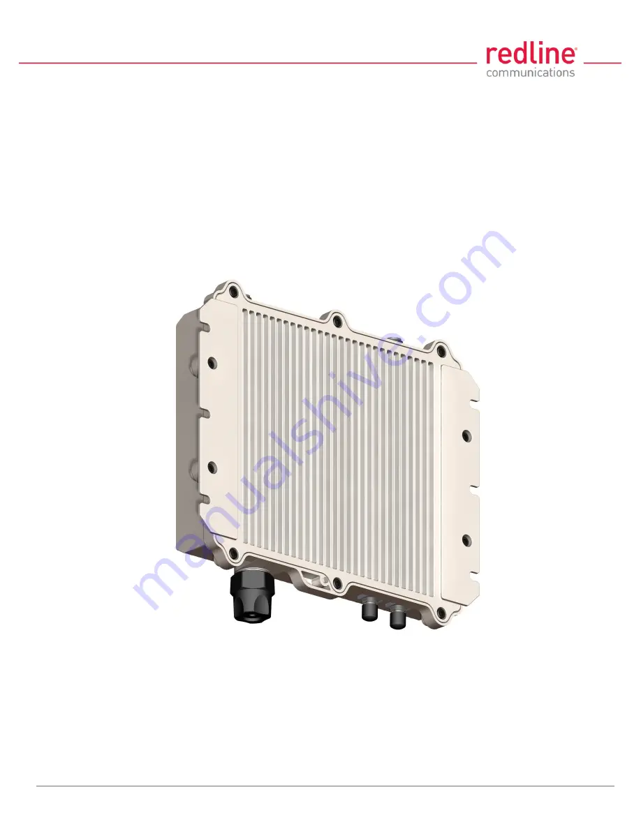
RDL-3000
Advanced Broadband Wireless
Infrastructure Solutions
User Manual
Страница 1: ...70 00158 01 DRAFT Proprietary Redline Communications 2010 Page 1 of 142 November 25 2010 RDL 3000 Advanced Broadband Wireless Infrastructure Solutions User Manual ...
Страница 2: ...m Media media redlinecommunications com Support support redlinecommunications com Training training redlinecommunications com Careers hr redlinecommunications com Document Control 70 00158 01 00 RDL 3000_User_Manual 20101125a doc Disclaimer The statements configurations technical data and recommendations in this document are believed to be accurate and reliable but are presented without express or...
Страница 3: ...2 5 RF Ports 18 2 6 Ground Lug 19 2 7 Audible Alignment 19 2 8 Management Interfaces 20 2 9 PoE Power Adapter 21 3 Functional Overview 22 3 1 Overview 22 3 2 PMP Mode 23 3 3 PTP Mode 38 4 Web Interface 39 4 1 Connecting With a Web Browser 39 4 2 System Menu 41 4 3 Dashboard Display 44 4 4 Status Screens 46 4 5 Configuration Screens 57 4 6 Provisioning Screens 74 4 7 Utilities Screens 86 5 CLI Inte...
Страница 4: ...ry Default Settings 121 6 5 Long Reset Recover from Lost Password or IP 123 7 Security 126 7 1 Overview 126 7 2 Wireless Authentication 127 7 3 AES Encryption 128 7 4 SSH for Secure CLI 129 7 5 HTTPS SSL for Secure Web 130 8 Appendices 132 8 1 Technical Specifications 132 8 2 Classification Services and Service Groups 134 8 3 Regional Codes 138 8 4 FCC IC Certified Antennas 140 ...
Страница 5: ...2 Ethernet Port 18 2 3 Synchronization I O Port PPS 18 2 4 GPS Antenna Port GPS ANTENNA 18 2 5 RF Ports 18 2 6 Ground Lug 19 2 7 Audible Alignment 19 2 8 Management Interfaces 20 2 8 1 Web Browser HTTP 20 2 8 2 Telnet CLI 20 2 8 3 SNMP 20 2 9 PoE Power Adapter 21 3 Functional Overview 22 3 1 Overview 22 3 2 PMP Mode 23 3 2 1 Subscriber Links 23 3 2 2 Services and Service Groups 24 3 2 3 Setting Wi...
Страница 6: ...ess Summary 49 Wireless Ethernet Statistics 49 Ethernet Port Statistics 49 4 4 3 Subscriber Links Summary Screen SC Only 50 4 4 4 Subscriber Link Status 51 General 51 Wireless 52 Wireless Packets 52 4 4 5 Subscriber Services Summary Screen SS Only 53 4 4 6 System Messages Log 54 4 5 Configuration Screens 57 4 5 1 System Screen 57 System Identification 58 Basic Ethernet Configuration 58 Advanced Et...
Страница 7: ...ervice Status 83 General 83 Ethernet Packets 83 4 6 7 Subscriber Service Configuration 84 Basic Service Configuration 84 Advanced Service Configuration 85 4 7 Utilities Screens 86 4 7 1 Spectrum Sweep 86 Spectrum Sweep Configuration 86 Spectrum Sweep Chart 87 Performing a Sweep 87 4 7 2 Users Management 88 System Users 89 Change User Settings 89 Add User 89 Delete User 89 4 7 3 Product Options 90 ...
Страница 8: ...120 6 3 1 Parameters Overview 120 6 3 2 Test Configuration Changes 121 6 4 Factory Default Settings 121 6 5 Long Reset Recover from Lost Password or IP 123 6 5 1 Long Reset Using Telnet 123 6 5 2 Restore Default Passwords Only 124 6 5 3 Restore Factory Configuration 124 7 Security 126 7 1 Overview 126 7 1 1 Authentication 126 7 1 2 Management Security 126 7 1 3 Data Security 126 7 1 4 Physical Sec...
Страница 9: ...Box Operation 130 7 5 2 Enable HTTPS SSL 130 7 5 3 Loading HTTPS SSL Certificate and Key Files 130 8 Appendices 132 8 1 Technical Specifications 132 8 2 Classification Services and Service Groups 134 8 2 1 Packet Classification at the Sector Controller 134 8 2 2 Packet Classification at the Subscriber 136 8 2 3 VLAN 802 1Q Fields 137 8 3 Regional Codes 138 8 4 FCC IC Certified Antennas 140 8 4 1 4...
Страница 10: ...get 100 Table 20 CLI load 103 Table 21 CLI logout 104 Table 22 CLI new 104 Table 23 CLI ping 104 Table 24 CLI reboot 104 Table 25 CLI reset 105 Table 26 CLI save 105 Table 27 CLI script 105 Table 28 CLI set 106 Table 29 CLI show 114 Table 30 CLI snmpcommunity 115 Table 31 CLI snmptrap 115 Table 32 CLI upgrade 116 Table 33 CLI user 117 Table 34 CLI whoami 117 Table 35 Diag Web Interface Diagnostics...
Страница 11: ... Tagged Management 30 Fig 16 PMP Operation VLAN Services Default Groups and Services 31 Fig 17 PMP Operation VLAN Services VLAN Mapping 32 Fig 18 PMP Operation Strict VLAN Tagging 33 Fig 19 PMP Operation TLS Extended TLS and Double Tagging 34 Fig 20 PMP Operation Tagged Traffic Designated Management Group 35 Fig 21 PMP Operation Tagged Traffic Port by Port Tagging 36 Fig 22 PMP Operation Tagged Tr...
Страница 12: ...Security Screen Subscriber 73 Fig 49 Web Links Screen Master List 74 Fig 50 Web Subscriber Link Configuration Screen 76 Fig 51 Web Service Groups Screen Master List 79 Fig 52 Web Service Group Status Screen 80 Fig 53 Web Service Group Configuration Screen 81 Fig 54 Web Service Status Screen 83 Fig 55 Web Service Configuration Screen 84 Fig 56 Web Spectrum Sweep Screen 86 Fig 57 Web Users Managemen...
Страница 13: ...uirements are indicated on the product marking label Do not exceed the described limits 6 Disconnect the power before cleaning or when the unit is not be in use for an extended period 7 The unit must not be located near power lines or other electrical power circuits 8 The system must be properly grounded to protect against power surges and accumulated static electricity It is the user s responsibi...
Страница 14: ... that can cause sensitive equipment to malfunction A good grounding system disperses most of the surge energy from a lightning strike away from the building and equipment The remaining energy on the Ethernet cable shield and conductors can be directed safely to ground by installing a lightning arrestor in series with the cable If you have determined that it is appropriate to install lightning prot...
Страница 15: ... pursuant to part 15 of the FCC Rules These limits are designed to provide reasonable protection against harmful interference in a residential installation This equipment generates uses and can radiate radio frequency energy and if not installed and used in accordance with the instructions may cause harmful interference to radio communications However there is no guarantee that interference will n...
Страница 16: ...en conformance avec les exigences finies de sûreté de sur tension sur les câbles de télécommunications un fil de télécommunication ayant un calibre minimum de 26 AWG doit être utilisé 5 Reminder to all the BWA system installers Attention to Section 820 40 of the NEC which provides guidelines for proper grounding and in particular specifies that the cable ground shall be connected to the grounding ...
Страница 17: ...l interference and enhanced security features that provide over the air encryption The RDL 3000 outdoor unit is housed in a weatherproof aluminum alloy case An indoor PoE power adapter provides operational power for the RDL 3000 and connection to the Ethernet network The outdoor unit can be used with a selection of antennas One RDL 3000 must be configured as a Sector Controller PMP SC to control a...
Страница 18: ... connector is installed Note The RDL 3000 synchronization feature must be used to minimize inter sector RF interference at any site where two or more base stations are deployed This feature synchronizes the transmit and receive cycles of collocated RDL 3000 base stations to minimize inter sector interference Up to four collocated base stations may be controlled using the synchronization cables A G...
Страница 19: ...tem Each 75 cm 29 5 in cable is terminated female N type to TNC Fig 4 Intro RDL 3000 RF Jumper Cables 2 6 Ground Lug A ground lug is provided on the RDL 3000 chassis Use this connection to terminate a grounding wire All RDL 3000 systems must be properly grounded to protect against power surges and accumulated static electricity 2 7 Audible Alignment When enabled the audible alignment signal chirps...
Страница 20: ... the RDL 3000 There is no logout command on the Web interface 2 8 2 Telnet CLI The RDL 3000 supports two concurrent Telnet sessions One session with full read write capabilities administrator and a second concurrent session with read only access e g monitor or show parameter settings To connect to the RDL 3000 CLI management open a Telnet session to the IP address of the RDL 3000 When the command ...
Страница 21: ...60 Hz Fig 6 Intro Indoor Power over Ethernet PoE Module AC Model Warning to Service Personnel 48 VDC Customer equipment including personal computers routers etc must be connected only to the INPUT DATA port on the PoE unit Only the outdoors Ethernet interface cable connecting to the RDL 3000 can be safely connected to the OUTPUT DATA POWER connector Connecting customer premises Ethernet equipment ...
Страница 22: ...ons are identical for both PTP and PMP operation The RDL 3000 can also be configured and monitored using SNMP documentation provided separately Note Refer to the RDL 3000 installation Guidelines for additional information about installing and operating the RDL 3000 in PMP mode Fig 7 PMP RDL 3000 Distributed L2 VLAN Aware Wireless Switch 3 1 Overview This section describes only the additional param...
Страница 23: ...affic received on a port The deployed RDL 3000 wireless network provides features of a standard wireless L2 bridge pass through mode and a VLAN aware wireless L2 switch tagged mode These features and other system capabilities are explained in the following sections 3 2 1 Subscriber Links Subscriber Links define the characteristics of the wireless interfaces between the sector controller and subscr...
Страница 24: ...n a port The following table lists the two methods to classify and process traffic received at the RDL 3000 Ethernet port Table 2 Web Operation Traffic Classification Type Function Settings Service Classify and process traffic received and transmitted over the subscriber Ethernet port Tagging Mode VLAN Pass through VLAN ID tag Default Priority Service Group Classify and process traffic received an...
Страница 25: ...s rate settings Fig 10 PMP Services Subscriber If the Ethernet port ingress packet has a VLAN tag and the VID matches a Service Group the VLAN tag is removed Q in Q and the packet is forwarded over the wireless interface Packets received over the wireless link are processed by the Service associated with the originating parent Service Group If the VLAN Tagging mode is tagged a VLAN tag with the Se...
Страница 26: ...t has a VLAN tag and the VID matches a Service Group the VLAN tag is removed Q in Q and the packet is forwarded over the wireless interface Unicast packets addressed to a Service Group member are forwarded only to that host subscriber Broadcast multicast and unknown unicast packets are forwarded to all Service Group members Packets received over the wireless link are processed by the parent Servic...
Страница 27: ...odulation and coding settings required to provide the selected rate Downlink UBR Uplink UBR Adaptive modulation mode Service Select the uplink and downlink Committed Information Rates CIR and peak Information Rates PIR rates for unicast traffic to from this subscriber Downlink CIR PIR Uplink CIR PIR Service Group Set the rates for downlink multicast and broadcast traffic belonging to this group Do...
Страница 28: ... Service Group or Service set to Pass through mode are forwarded without modification Pass through mode can be used to Transparently forward all unclassified traffic between two ports both ports are Pass though mode Add or remove the outermost VLAN tag Q in Q depending on the direction of the traffic only one port is using Pass though mode Fig 13 PMP Pass through Mode Notes 1 Only one Service Grou...
Страница 29: ...n another subscriber in the same sector Unicast traffic is forwarded to the sector controller and then retransmitted unmodified over the wireless interface to the destination subscriber Broadcast and multicast traffic is forwarded to the sector controller and processed by the parent Service Group of the originating Service Fig 14 PMP Subscriber to Subscriber Unicast Traffic Notes 1 SS to SS broadc...
Страница 30: ...classify the management traffic and a member Service for each participating subscriber The Service Group and member Services should all specify the same VID Select CIR and priority values that ensure adequate bandwidth and priority for management traffic during normal system operation For network security over the air management is only available from the sector controller For initial installation...
Страница 31: ...and Services Fig 16 displays an example of VLAN usage where all traffic not classified to the Voice Group is classified to the Data Group The Voice Group and Services are configured for tagged traffic and the Data Group and Connections are configured for pass through mode Note This configuration does not enforce a Service Group to have a Service on every subscriber or be enabled to the sector cont...
Страница 32: ...the VLAN tag for Voice C is set to VID 777 Ingress packets with VID 3 received on the sector controller Ethernet port are classified to the Voice Group These packets are forwarded over the wireless interface to members of this Service Group based on packet destination address Packets addressed to subscriber A or B will be tagged with VID 3 while packets addressed to subscriber C will be tagged wit...
Страница 33: ... displays an example of VLAN usage where only tagged traffic is allowed to pass through the system If a Subscriber port has no pass through connection or the Sector Controller port has no pass through group then that port does not accept untagged traffic or tags that are not explicitly configured Fig 18 PMP Operation Strict VLAN Tagging ...
Страница 34: ...tagged by a user specified VID referred to in this example as TLS VID This solution allows unmodified traffic to be exchanged between Network B Network C and a remotely located network called TLS Network If Subscriber B receives a tagged Ethernet packet from Network B or Subscriber C receives a tagged Ethernet packet from Network C the packet will exit the Sector Controller port double tagged Q in...
Страница 35: ...affic Using a Designated Management Group Fig 20 describes a system management scenario where management traffic is tagged at the Sector Controller as well as the Subscribers The system will map change the VLAN tags depending on the ingress and egress ports Fig 20 PMP Operation Tagged Traffic Designated Management Group ...
Страница 36: ...sed on the source or destination subscriber For every tag at the Sector Controller a distinct group is defined and each group has exactly one connection on the required link Subscriber port Note that the tagged port is not necessarily the Sector Controller port and may be one of the Subscriber ports Note also in Fig 21 that tagged traffic entering one of the Subscribers exits the Sector Controller...
Страница 37: ...of 142 November 25 2010 Tagging Groups of Ports Fig 22 displays an extension of the previous port by port tagging example where a group can have more than one connection i e the same tag extends over a number of Subscriber ports Fig 22 PMP Operation Tagged Traffic Tagging Groups of Ports ...
Страница 38: ...a single point to point connection A separate range of RF power settings are provided for PTP operation The GUI and Telnet functions are identical for PTP and PMP operation It is required to configure one unit as the controller PMP SC and one unit as a remote PMP SS The graphical user interface GUI and Telnet functions are identical for both PTP and PMP operation Note Refer to the RDL 3000 install...
Страница 39: ...n from the RDL 3000 Ethernet port to the PoE and the Ethernet Cat 5e crossover cable from the PoE to the PC Fig 24 Web Connecting a PC to the RDL 3000 Important Notes 1 The system must be properly grounded to protect against power surges and accumulated static electricity 2 When configuring the RDL 3000 in sector controller mode PMP SC the RF ports must be properly terminated to a dummy RF load or...
Страница 40: ... same subnet as the RDL 3000 For example IP address 192 168 25 11 Net Mask 255 255 255 0 2 On the PC open a browser and enter the unit RDL 3000 IP address The factory default IP address is 192 168 25 2 3 Enter the username and password to login The factory default username is admin and the default password is admin Fig 25 Web Login Screen 4 If the login was successful the General Information scree...
Страница 41: ...010 Page 41 of 142 November 25 2010 4 2 System Menu 4 2 1 Sector Controller and Subscriber Menus The following functions are available for configuring and monitoring the RDL 3000 Sector Controller Menu Subscriber Menu Fig 26 Web Main Menus for Sector Controller and Subscriber ...
Страница 42: ...tatus messages Configuration System System Configuration View and adjust system and network settings RADIUS RADIUS Configuration View and adjust RADIUS server settings SNMP SNMP Configuration View and adjust SNMP settings Wireless Wireless Configuration View and adjust wireless settings Frequencies Frequency Management View and adjust RF scanning lists Security Security Configuration View and adju...
Страница 43: ...All X Delete all Links Service Groups and Services Utilities Reboot Reboot the RDL 3000 Spectrum Sweep Spectrum Sweep Scan for interference Users Management Users Management Manage user accounts and passwords Firmware Firmware Management Upload new firmware Test Test for 5 minutes and then restore the last saved configuration no reboot Antenna Alignment Antenna Alignment X Display RSSI readings Pr...
Страница 44: ... through use of the Test function Click Save All in the main menu to save the current running configuration This configuration will be restored on power up reboot or the end of a test cycle Saving The system is saving the runtime parameters to non volatile RAM Radio Temperature Internal temperature of the radio 4 3 2 Wireless Leds These LED indicators provide a summary of the wireless status Link ...
Страница 45: ... an Ethernet connection and no traffic and blinks when traffic is detected 100 LED The Ethernet 100 LED lights solid green when the Ethernet port is operating at 100 Mb s and the LED is off when operating at 10 Mb s FD LED The FD LED lights solid green when the Ethernet connection is operating in full duplex mode and blinks when collisions are detected on the Ethernet port ...
Страница 46: ...lays the factory installed radio type Refer to section 8 1 System Specifications System Mode Operating mode of this unit PMP SC Operating as a sector controller the RDL 3000 begins transmitting automatically sends poll messages to locate and register remote subscribers and negotiates operating settings for each subscriber PMP SS Operating as a subscriber the RDL 3000 monitors the selected channel ...
Страница 47: ... 2010 Page 47 of 142 November 25 2010 Ethernet Ethernet MAC Address MAC address of the network interface on this unit IP Address Network IP address for this unit IP Subnet Mask Network IP subnet mask Default Gateway Address Network IP address of the default router or gateway ...
Страница 48: ... scheduling requirements A positive value indicates that surplus bandwidth is available Wireless Security Status of the wireless security selection Off No wireless security On Data sent over the wireless interface is encrypted DFS Status of the DFS function Off The DFS function is disabled On DFS function is activated See DFS Action below DFS Action The avoidance action to be taken when radar sign...
Страница 49: ...ess interface excluding discarded and errored packets Rx Received wireless packets Tx Transmitted wireless packets Discarded Packets Number of packets discarded by the local unit Rx Received wireless packets discarded buffer overflow Tx Transmitted wireless packets discarded by the local unit due to errors e g buffer overflow or unacknowledged by remote end unit Lost Packets Total number of packet...
Страница 50: ...ailable The link or Service is unavailable offline or disabled SINADR dB Ratio of the average RF signal strength to interference noise and distortion DL SINADR reported by the remote end unit UL Received signal strength to noise measured by this unit RSSI dBm Received signal strength indicator DL RSSI reported by the remote end unit UL Received signal strength measured by this unit Burst Rate Mb s...
Страница 51: ...display this screen SS Click Link Status in the main menu to view the status of the wireless link for this subscriber Fig 32 Web Subscriber Link Status Screen General Subscriber Link Name User assigned name for this link Subscriber Link ID Unique number identifying this link Subscriber MAC MAC Address of the subscriber Active Indicates if wireless link is operational Active YES Link Up Time Total ...
Страница 52: ...transmitted Total number of wireless packets that have been retransmitted over the wireless interface Lost Total packets discarded by the local system due to errors SINADR dB Ratio of the average RF signal strength to interference noise and distortion DL SINADR reported by the remote end unit UL Received signal strength to noise measured by this unit RSSI dBm Received signal strength indicator DL ...
Страница 53: ... Service is available The Link or Service is unavailable offline or disabled Click the status to display the Subscriber Service Status screen Discarded Packets Total number of packets discarded by the local system due to errors UL Received wireless packets discarded DL Transmitted wireless packets discarded by remote end unit Tx Packets Total packets successfully transmitted over the wireless inte...
Страница 54: ...ystem messages Table 5 Web System Log Messages Event ID Event Description 1001 System Configuration Load OK 1002 System Configuration Save OK 1003 EEPROM Directory Load OK 1004 EEPROM Directory Save OK 1005 User Configuration Load OK 1006 User Configuration Save OK 1007 Network Configuration Load OK 1008 Network Configuration Save OK 1009 Network Configuration OK 1010 Version Ctrl Data Load OK 101...
Страница 55: ...or 2002 System Configuration Save Error 2003 EEPROM Directory Load Error 2004 EEPROM Directory Save Error 2005 User Configuration Load Error 2006 User Configuration Save Error 2007 Network Configuration Load Error 2008 Network Configuration Save Error 2009 Network Configuration Error 2010 Version Ctrl Data Load Error 2011 Version Ctrl Data Save Error 2012 System Description Load Error 2013 System ...
Страница 56: ...Certificate missing using default one 2066 SSL KEY missing using default one 2070 Pre Shared Key ERROR 2071 Authentication Packet Validation ERROR 2072 Encryption Key Validation ERROR 2073 Signature Validation ERROR 2074 Certificate Validation ERROR 2075 RNG self test ERROR 2076 DSA pair wise test failed 2077 RNG self test failed 2078 TDES self test failed 2079 AES self test failed 2080 SHA self t...
Страница 57: ...tion Screens 4 5 1 System Screen Click Configuration System in the main menu to view and adjust configuration settings for system identification and Ethernet settings This screen is identical for the sector controller and subscriber units Click to expand or to hide fields Fig 35 Web Config PMP SC System Configuration Screen ...
Страница 58: ...nly 10Mbps FD Operate at 10Base T full duplex only 100Mbps HD Operate at 100Base T half duplex only 100Mbps FD Operate at 100Base T full duplex only Important The auto negotiate function works correctly only when both communicating Ethernet devices are configured for auto negotiate The auto negotiate feature does not detect the speed and duplex of Ethernet equipment operating at a fixed speed and ...
Страница 59: ...nforced When Local RADIUS or RADIUS Only is selected click on the main menu item RADIUS to display the RADIUS Configuration screen Note When user authentication is set to RADIUS Only or Local RADIUS the authorization data is retrieved from the RADIUS server at 10 minute intervals For example if a user s authorization is changed on the RADIUS server it may require up to ten minutes before the RDL 3...
Страница 60: ...t If the Management VLAN Tagging feature is required it is recommended to test the VLAN connectivity before activating this function Otherwise the RDL 3000 unit may become unmanageable require a long reset operation to recover control Fig 36 Web VLAN Tagged Management Example In the following example the network management VLAN ID 600 Identical settings are used on the Service Group and each subsc...
Страница 61: ...P address Server Auth port Listening port address on RADIUS server default port is 1812 Shared secret Password for RADIUS server Must conform to security policy Request retries Maximum number for attempts to contact target RADIUS server Request time out Time to wait for response from RADIUS server seconds When using a FreeRadius server the following files must be modified on the RADUIS server plat...
Страница 62: ... eight separate community strings Each community name is assigned specific access rights read write The public and private community strings are default access values and should be changed to secure system access Community Name SNMP community name for this entry Access Access permissions for this entry None No access permissions for this entry Read Read access permission only for this entry Deny w...
Страница 63: ...s Select the access permissions for this entry None Deny read and write permission for this entry Read Grant read access permission only for this entry Deny write permission Write Grant write access permission only for this entry Deny read permission Read Write Grant read and write access permission for this entry Change Community Click to accept the displayed settings and return to the SNMP Confi...
Страница 64: ...mission for this entry DES DES Data Encryption Standard is an encryption standard AES AES Advanced Encryption Standard is an encryption standard Update Configuration Click to accept the displayed settings and return to the SNMP Configuration screen Clicking does not activate changes SNMP Trap Destination Settings This section of the SNMP Configuration screen displays the SNMP trap destination sett...
Страница 65: ...vate changes SNMP Trap Settings SNMP Traps Enabled Control the SNMP trap message function Disabled The RDL 3000 does not send SNMP trap messages Enabled The RDL 3000 sends SNMP trap messages Link Up Down Trap Enabled Control SNMP trap messages for the link status Disabled The RDL 3000 does not send SNMP trap messages based on changes to the wireless link status Enabled A trap message is sent for e...
Страница 66: ...ic Wireless Configuration System Mode The system designated as sector controller establishes and manages the bi directional data link with a remote end RDL 3000 Only one system in a wireless link must be set for Sector Controller mode PMP SC PMP SC RDL 3000 automatically sends poll messages to locate and register remote RDL 3000 subscribers and negotiates operating settings for the link PMP SS RDL...
Страница 67: ... is not enabled the wireless link can be established only at the frequency specified in the RF Freq MHz field By default the subscriber will scan the entire frequency band enabled by the options key see section 8 3 Regional Codes on page 138 To reduce the scanning connection time the operator may specify a subset of frequency ranges to scan Click on the main menu item Configuration Frequencies to ...
Страница 68: ...frequency This action is logged and a trap message is sent if enabled A new channel is selected based on allowable frequencies for the regulatory region set by the active options key Each selected channel is monitored for one minute and if DFS triggering events are detected the next available channel is selected The system is not allowed to return to a channel on which DFS trigger events were dete...
Страница 69: ...GPS module is installed and synchronized to one or more satellites transmissions are synchronized to the module 1 PPS output External Synchronize this unit to a 1 PPS signal received on the PPS port Synchronization Output SC only When Fixed Frame mode is selected the synchronization output port PPS mode must be specified Disabled The PPS port is disabled Enabled The synchronization port output is ...
Страница 70: ... controller and subscriber units Click to expand or to hide fields Fig 46 Web Frequency Management Screen PMP SC The sector controller can be programmed with a master list of frequency ranges When a subscriber registers with the sector controller this list is automatically downloaded to the subscriber and displayed as the Remote Frequency Ranges Subscribers with Auto Scan enabled use these downloa...
Страница 71: ...en Delete Frequency Range Index Choose the index value of the scan interval to be deleted from local frequency range table Delete Click to permanently remove the selected index scan interval Local Frequency Ranges These settings are saved in non volatile memory and loaded when the unit is rebooted Index Index value of this entry in the local frequency range table Begin Lower limit of the frequency...
Страница 72: ...ector This is required only when encryption is enabled Shared key confirmation Re enter key to minimize errors This field must be identical to the Shared Key field X 509 Authentication Enable Check this box to require authentication using an installed X 509 certificate The user defined unit certificate authority certificate and RSA private key must be downloaded using the CLI load command Uncheck ...
Страница 73: ...g 48 Web Wireless Security Screen Subscriber Notes 1 Clicking on another main menu item before clicking Apply or Apply Save All will discard any changes made to settings displayed on the current screen 2 HTTPS SSL is not available until an X 509 certificate and DSA private key have been loaded ssl_cert_ mac pem and ssl_key_ mac pem 3 AES encryption is not available until the X 509 certificate and ...
Страница 74: ...ing the CLI interface to modify provisioning settings Status Graphic indication of the status of this Link or Service The Subscriber Link or Service is available online The Subscriber Link or Service is unavailable offline or disabled Click the Link status to display the Subscriber Link Status screen Click the Service status to display the Subscriber Service Status screen Parent Group The Service ...
Страница 75: ...ed available downlink bandwidth based on scheduling cycle DL Unicast Kbps Unicast traffic downlink rates CIR Requested minimum committed downlink bandwidth OIR Available downlink bandwidth based on scheduling cycle UL Unicast Kbps Unicast traffic uplink rates CIR Requested minimum committed uplink bandwidth OIR Calculated available uplink bandwidth based on scheduling cycle ...
Страница 76: ...and statistics screens The name may contain up to fifteen alpha numeric characters including a z A Z 0 9 dash and underscore _ Link ID Read only A unique numeric ID generated automatically when the Subscriber Link is created This value is required when using the CLI interface to modify SNMP settings Subscriber MAC Enter the MAC address of the subscriber for this wireless link The sector controller...
Страница 77: ...rate falls below this threshold the affected rate statistics are displayed in red Subscriber Links Summary screen and the downlink PIR for all Services Service Groups are reduced proportionally until the condition clears Note Adjustments to modulation and coding cause temporary changes to the PIR of all connections on that wireless link This ensures degradation of the RF signal on any wireless lin...
Страница 78: ...ncy or dropped packets buffer full condition DL Burst Rate Downlink burst rate for unicast traffic The RDL 3000 will establish a wireless link only at the specified rate The communicating wireless unit must also be operating at the same fixed rate UL Burst Rate Uplink burst rate for unicast traffic The RDL 3000 will establish a wireless link only at the specified rate The communicating wireless un...
Страница 79: ...y when the Service Group or Service was created This value is required when using the CLI interface to modify Service Group or Service settings Status The status of this Service Group or Service Service Group or Service is available Service Group or Service is unavailable down offline Click the Service Group status to display the Service Group Status screen Click the Service status to display the ...
Страница 80: ...Web Service Group Status Screen General Service Group Name Name of the Service Group Service Group ID A unique numeric ID for this Service Group This value is required when using the CLI interface to modify Service Group settings Broadcast Ethernet packets Discarded Packets Total packets discarded by the local system due to errors Transmitted Packets Total broadcast or multicast packets successful...
Страница 81: ...cs screens The name may contain up to fifteen 15 alpha numeric characters including a z A Z 0 9 dash and underscore _ Service Group ID Read only A unique numeric ID generated automatically when a Service Group is created This value is required when using the CLI interface to modify Service Group settings VLAN Tagging Select the classification mode for this Service Group Tagged Select tagged to ass...
Страница 82: ...erface Burst Rate Enter the uncoded burst rate for downlink broadcast and multicast traffic belonging to this Group Use the Auto setting recommended to have the rate selected automatically based on the current operating conditions To set this to a fixed value first identify the group member having the lowest Max DL Burst Rate setting and then calculate the rate using the formula Burst_Rate Max DL ...
Страница 83: ... A unique numeric ID generated automatically when the Service was created This value is required when using the CLI interface to modify Service settings Ethernet Packets Packets Discarded Total number of packets discarded by the local system due to errors Rx Received wireless packets discarded Tx Transmitted wireless packets discarded by remote end unit Packets Transmitted Total packets successful...
Страница 84: ...k hosting this Service and then click the Service name Name field The Service Configuration screen is displayed and the fields can be updated Click to expand or to hide fields Fig 55 Web Service Configuration Screen Basic Service Configuration Service Name Enter a name for this Service 15 characters maximum The Service name is displayed on configuration and statistics screens Parent Subscriber Lin...
Страница 85: ...downlink unicast traffic UL PIR Enter the peak information rate for uplink unicast traffic The traffic each Service transmits over the wireless interface is monitored to enforce PIR settings 50 50000 Kbps Traffic statistics are reset at the beginning of each common one second clock tick If the maximum throughput is reached on any Service before the end of the current interval that Service is exclu...
Страница 86: ...frequency limits the step size and the number of samples at each step The output graph displays the average dark green and maximum light green RSSI measured at each step Fig 56 Web Spectrum Sweep Screen Spectrum Sweep Configuration Start Frequency MHz Enter center frequency of the lowest channel to be scanned End Frequency MHz Enter center frequency of the highest channel to be scanned Step MHz En...
Страница 87: ...ration of the test 2 Click Wireless Spectrum Sweep in the main menu It is recommended to scan using the smallest available channel with a step size of 1 2 the planned channel size e g use a 5 MHz step size when scanning for a free 10 MHz channel For example Start Stop 5735 5830 Step MHz 5 No of Acquisitions 10 3 Click Start button to begin the sweep 4 Review the results A channel may be considered...
Страница 88: ...ssociated with each group Administrators can add new user accounts and modify passwords Usernames may be 1 to 19 alpha numeric characters including a z A Z 0 9 dash and underscore _ Passwords may be 8 to 15 alpha numeric characters including a z A Z 0 9 dash and underscore _ Important There must always be at least one administrator account active on the RDL 3000 You can not manage the RDL 3000 if ...
Страница 89: ...r Enter the name of the administrator authorizing this change Admin Password Enter the administrator password Change Click to activate and permanently save changes Add User Use these controls to create a new account Name Enter a name for the new user account New Password Enter a password for the new account Confirm Password Re enter the password for the new account Admin User Enter the name of the...
Страница 90: ...ve days of operation Fig 58 Web Product Options Screen Options Key 1 Enter a valid permanent key A permanent Options Key must be entered for in Service operation The temporary options key shipped with the RDL 3000 will expire and Service is interrupted Options Key 2 Enter a second valid permanent or temporary options key optional Active Options Key The Active Options Key field selects the preferre...
Страница 91: ...VLAN for Data Classification Disabled VLAN for Management Disabled Wireless System Mode PMP SS Only Channel Width 10 MHz RF Freq T502 radio MHz 3300 3800 3650 3700 4400 5000 4940 4990 5150 5250 5495 5600 5650 5725 5725 5795 5815 5850 Auto Scan Disabled Tx Power 10 dBm max DFS Permanently Enabled Security AES Disabled Secure Management HTTPS SSH SNMPv3 Disabled X 509 Authentication Disabled Provisi...
Страница 92: ...mum performance from a wireless link is by fine alignment of the antenna to the position providing the highest RSSI Received Signal Strength Indication This web page assists alignment by providing continuous updates of the current measured RSSI value Fig 59 Web Antenna Alignment Tool Screen If Wi Fi service is available you may also be able to access the web alignment page directly from a laptop c...
Страница 93: ...native This is the inactive firmware Firmware downloaded to the RDL 3000 will overwrite this version Change Version Click to switch the Active and Alternative firmware versions and reboot the RDL 3000 Firmware Upgrade Transfer Protocol Select the type of file server TFTP Use Trivial File Transfer Protocol for file upload FTP Use File Transfer Protocol for file upload Server IP Address Enter the IP...
Страница 94: ...ding the bin extension If FTP is selected enter account name and password 3 Click Upload File to begin the file transfer The transfer may require up to eight minutes based on the data transfer rate Do not interrupt the transfer process When the transfer is complete the RDL 3000 checks the integrity of the uploaded file and registers a status message in the event log If errors were introduced durin...
Страница 95: ...92 168 25 11 Net Mask 255 255 255 0 5 1 Telnet Access Use the following steps to establish a Telnet session with the RDL 3000 Refer to the RDL 3000 User Manual section 5 CLI Interface for a complete description of the available commands 1 On the PC open a Telnet client and enter the unit IP address The factory default IP is 192 168 25 2 2 Login to the RDL 3000 using the assigned username and passw...
Страница 96: ...configuration settings script Generate a configuration script set View modify a system parameter value show View system compound objects e g configuration snmpcommunity View modify the SNMP community settings snmptrap View modify the SNMP trap settings upgrade Upload a firmware binary image to the RDL 3000 user View modify the user password configuration whoami Display login name for this Telnet s...
Страница 97: ...ave config command to permanently save changes to the static entries in the ARP table Static entries loaded at boot time are recorded in the RDL 3000 system log Table 12 CLI arp arp add del print add Host MAC Add a new static entry in the RDL 3000 ARP table Use save config to save these entries permanently A maximum of two static entries can be added to the table Host Host IP address Must be same ...
Страница 98: ...Delete all static entries in the ARP table refer to arp freqlist Delete all frequency ranges from list refer to freq command idtable Delete all IDs from the idtable log Delete all messages from the log 5 3 5 del Use the del command to delete a specific ID or security key certificate Table 15 CLI del Delete file information from the RDL 3000 non volatile memory del file folder id file name mode Rem...
Страница 99: ...to enable a specific ID that was disabled Table 16 CLI enable Enable a Service Group Service or Link id enable id Enable a specific ID id Unique number for Service Group Service or Link 5 3 7 freq Use the freq command to configure frequency ranges when using autoscan or DFS Table 17 CLI freq freq add clearall del print reload add begin end Add a frequency range up to 32 ranges begin start frequenc...
Страница 100: ...stem parameters Use the following general format to view a parameter Table 19 CLI get Display parameters get parameter activeids Number of active IDs Services Service Groups and Links activelinks Number of active Links dldpkt Number of downlink discarded packets dloir id Get the downlink offered information rate for the service dlrpkt Number of downlink Rx packets dltpkt Downlink Tx packets erxpkt...
Страница 101: ...Downlink burst rate ldldblk Downlink discarded blocks ldllfr Downlink lost frames ldlrblk Downlink retransmitted blocks ldlrssi Downlink RSSI ldlsnr Downlink SINADR llostc Wireless link lost lrcon Number of Services provisioned on this Link lrsrv Number of links with registered service connections lscode Link status code lulblk Uplink total blocks lulbr Uplink burst rate luldblk Uplink discarded b...
Страница 102: ...rfstatus Status RF transmitter swver List the downloaded firmware versions sysstarttime Time when the system started sysuptime Time elapsed from reboot temperature Internal temperature of the radio txpower Current Tx power setting uldpkt Uplink discarded packets uloir id Get the uplink offered information rate OIR for the service ulrpkt Uplink Rx packets ultpkt Uplink Tx packets werxpkt Wireless E...
Страница 103: ...r wireless certificate usr_wkey_ mac der User wireless key usr_wacert_ mac der User wireless authority certificate The mac portion is the MAC address of the board For example dsa_key_00 09 02 00 01 02 pem Specify where to store the security information usr User entered files default if type is not specified factory Default files fips FIPS mode files FIPS mode must be active For example load file 1...
Страница 104: ... initiate an ICMP ping command from the RDL 3000 Table 23 CLI ping Send an ICMP ping command This can be used to confirm network access to FTP TFTP servers syslog servers etc ping IP address Number of Packets IP address IP address of target Number of Packets Number of ICMP packets to send 1 to 16 5 3 14 reboot Use the reboot command to reboot the RDL 3000 firmware Table 24 CLI reboot Command the R...
Страница 105: ... location details and contact frequency list SNMP configuration Idtable idtable Save current idtable settings snmp Save current SNMP settings 5 3 17 script Use the script command to save a file containing a string of Commands that can be used to restore the current active configuration of the RDL 3000 Saved configuration files can be viewed copied and or modified using a text editor The file is sa...
Страница 106: ...disable the adaptive modulation function off Disable on Enable antgain gain Set the antenna gain used for DFS gain Enter gain in dBm autoscan off on Enable or disable the Autoscan function off Disable on Enable When enabled the Subscriber automatically scans available channels to locate the current operating frequency bsmac 00 00 00 00 00 00 mac_address If set to a non zero value the subscriber is...
Страница 107: ...r signals are detected This action is recorded in the message log and an SNMP trap message is sent if SNMP enabled Chg Freq 2 Relocate transmission to an alternative frequency immediately when radar signals are detected This action is recorded in the message log and a trap message is sent if SNMP enabled dlminrate id 1 54 Link minimum downlink uncoded burst rate Mbps Entry values are dependent on ...
Страница 108: ...the framesize field framesize size When Fixed Frame is enabled enter the frame size in milliseconds size Enter the fixed frame size ms gateway ip Enter the IP address of the default gateway on this segment gmt value Enter the time offset from GMT e g 5 for EST grpcir id 50 50000 Service Group Committed Information Rate CIR for downlink broadcast and multicast traffic id Group ID number grppir id 5...
Страница 109: ... mask Enter the IP address and subnet mask of the RDL 3000 Confirmation is required Example set ipaddr ip 192 168 100 10 mask 255 255 255 0 ldlpir id 50 50000 Link downlink PIR id Link ID number lulpir id 50 50000 Link uplink PIR id Link ID number maxdst distance Maximum distance to a subscriber value Distance Km to farthest subscriber maxtxpower 10 25 Enter the Tx power level dBm This setting is ...
Страница 110: ...mits radius ip mode port retries secret timeout Configure the RADIUS server allowed in FIPS mode The first parameter for all commands must be the radius server identifier 1 or 2 ip 1 2 IP address IP address of RADIUS server 1 Primary RADIUS server 2 Secondary RADIUS server For example Set the primary RADIUS server IP address and then set the secondary RADIUS server IP address set radius ip 1 192 1...
Страница 111: ...P traps off Disable all SNMP trap messages on Enable all SNMP trap messages sntp off on SNTP enable setting off Disable SNTP protocol support on Enable SNTP protocol support sntpip ip Enter the SNTP server IP address Valid only if sntp is enabled sntppoll 1 24 Enter the SNTP polling interval in hours Enter period in hours ssh off on Enable or disable the SSH function off Disable on Enable sstoss i...
Страница 112: ...t termination impedance is 50 Ohms 75 Port termination impedance is 75 Ohms syscontact text Enter contact descriptive for this RDL 3000 Enter up to thirty 30 alpha numeric characters including a z A Z 0 9 dash and underscore _ sysdescr text Enter system description for this RDL 3000 Enter up to thirty 30 alpha numeric characters including a z A Z 0 9 dash and underscore _ sysloc location Enter loc...
Страница 113: ...ult is 23 Changes to this field are effective only following reboot ulcir id 50 50000 Enter the uplink committed information rate for the service Kbps id id number ulminrate id 6 54 Link minimum downlink uncoded burst rate id Link ID number ulpir id 50 50000 Service uplink peak information rate PIR Kbps id Service ID number ulrate id 1 54 Link maximum uplink uncoded burst rate id Link ID number us...
Страница 114: ...usr Display the user keys and certificates default groups Display information for all Service Groups 192 168 25 2 show groups 64 Voice Group 65 Data Group idtable Display information for all system IDs 192 168 25 2 show idtable ID Name Type Status 4 Sub A Link Enabled 5 Sub B Link Enabled 10 Sub C Link Enabled 15 Sub D Link Enabled 64 Voice Group Enabled 65 Data Group Enabled 96 Data A Conn Enable...
Страница 115: ...on enter zero r Grant read access permission only w Grant write access permission only rw Grant read and write access permission clearall no parameters Delete all SNMP parameters default idx Set all SNMP parameters to factory default settings idx Specify single entry to be set to default use print command to display ids del idx Delete the specified community entry idx Specify single entry to be de...
Страница 116: ...ay ids Linkupdown Trap indicates when the wireless Link is lost and recovered Off On print List all SNMP trap settings 5 3 22 upgrade Use the upgrade command to upload a new firmware binary file to the RDL 3000 Table 32 CLI upgrade Configure SNMP community permissions upgrade ip addr file name user name password ip addr IP address of the FTP TFTP server file name Name of the binary file to be uplo...
Страница 117: ...eens and User Access on page 42 for permissions associated with each group username Enter name of new administrator or user account usertype Specify the type of account being created user User account admin Administrator account attr username none MD5 SHA none DES AES Designate an authentication method and privacy method to be used for SNMP v3 requests An authentication method must be selected to ...
Страница 118: ...cessful there may be problems using that IP address the IP address may be incorrect or there may be a duplicate address For correct operation the host computer and the RDL 3000 must be on the same subnet For example if the RDL 3000 is using the factory default settings the host computer could be set for an IP of 192 168 25 3 and a subnet mask of 255 255 255 0 If the correct IP address of the RDL 3...
Страница 119: ...ic calculator that supports binary notation e g Windows on screen calculator Set the mode for Hex and enter the status code Change the mode to binary and match active bits 1 to the PMP Status Codes table For example if Radio Over Temperature bit 1 and PLL Error bit 4 were active the status code value would be Hex 12 binary 1 0010 Table 36 Diag PMP Status Code Bits 31 30 29 28 27 26 25 24 23 22 21 ...
Страница 120: ...ify these values Activate changes by using the apply function Save changes permanently by using the save functions Saved Parameters These values are saved in non volatile RAM and are loaded at reboot Use the save function to overwrite the last saved settings with the current contents of the Editing Copy of Parameters A separate copy of Saved Parameters is maintained for each firmware version Activ...
Страница 121: ... setting are satisfactory use save config to save these settings and reboot 0 to cancel the timed reboot operation 6 4 Factory Default Settings Use the Web interface click Factory Defaults in main menu or the CLI interface save defaultconfig to restore the RDL 3000 to a known state Table 38 Diag Factory Default Settings CLI Parameter Web Field Option Key Def Cfg Button Setting System syscontact Sy...
Страница 122: ...tion Y Based on Key No Key chgfreq Required chgfreq Not Req none dlratio Downlink Ratio No change pskey Pre shared key No change fixframe Fixed Frame Mode Off framesize Framing Cycle 1 maxdst Max Distance 0 radio Radio Enable rf1 regper Registration Period 16 rffreq RF Freq MHz Based on key T502 5800 schcycle Scheduling Cycle 2 syncmode Synchronization mode None syncout Sync port mode None port di...
Страница 123: ...portunity to login to the RDL 3000 using the default IP usernames and passwords The long reset procedure requires local access to the RDL 3000 PoE adapter to power cycle the RDL 3000 and a PC with an Ethernet cable and a Telnet client or Web browser Fig 63 Diag Recovering Lost IP Address 6 5 1 Long Reset Using Telnet Use the following steps to gain access to the RDL 3000 management interface It is...
Страница 124: ...eset Using Telnet substituting the Web browser for Telnet 6 5 2 Restore Default Passwords Only Use this procedure if the unit IP address is known and it is desired only to restore the default usernames and passwords All other configuration settings are preserved Telnet 1 Perform a long reset and use Telnet to login to the RDL 3000 using the default IP address 192 168 25 2 and the default administr...
Страница 125: ...se a Web browser to login to the RDL 3000 using the default IP address 192 168 25 2 and the default administrator username admin and password admin 2 Click Configuration System to display the System Configuration screen 3 Click on the Def Cfg button at the bottom of the screen to reload the factory settings and automatically reboot the RDL 3000 4 Wait for the reboot to complete 10 seconds and logi...
Страница 126: ...ption decryption for data traffic Messages encrypted and validated using AES in CCM Counter with Cipher Block Chaining Message Authentication Code Key derivation with separate keys for data traffic and key transport Diffie Hellman for key establishment AES Wrap algorithm for key transport Keys changed at random intervals AES Advanced Encryption Standard option is an encryption standard used worldw...
Страница 127: ...generate and load X 509 certificate and key files 2 The wireless certificate and key files must be loaded into the user usr table The files can only be loaded using the CLI interface Telnet or SSH Reboot the RDL 3000 to activate the certificate and key 3 Configure and activate authentication services 7 2 2 Generate X 509 Certificate and Key Files Use a commercially available tool to create the req...
Страница 128: ...hased separately AES encryption is not supported on RDL 3000 systems 7 3 1 Out of Box Operation AES encryption is not supported out of box Each RDL 3000 system to be use AES encryption must meet the following requirements 1 AES 128 bit An options key enabled for AES 128 bit operation must be obtained no charge loaded on the RDL 3000 and be the currently active options key AES 128 bit operation is ...
Страница 129: ... settings e g Warning Potential Security Breach The servers host key does not match The operator has full access to the secure CLI interface 7 4 2 Enable SSH SSH is disabled by factory default Use the CLI or Web interface to enable SSH Web interface Configuration screen Ethernet SSH Enable CLI Command set ssh on 7 4 3 Loading an SSH Key File Use the following steps to load user generated X 509 cer...
Страница 130: ...d by a trusted certificate authority The security certificate presented was issued for a different website address The operator has full access to the secure Web interface It is recommended that system operators generate a unique certificate and private public keys and load these on the RDL 3000 before using the HTTPS feature in a production environment 7 5 2 Enable HTTPS SSL HTTPS is disabled by ...
Страница 131: ...ave been successfully loaded 5 Reboot the RDL 3000 to activate changes to the key files HTTPS is available when the system reboot is completed Example Load HTTPS SSL key and certificate files from the TFTP server at 192 168 25 1 to the RDL 3000 having MAC address 00 09 02 01 C1 9A 192 168 25 2 load file 192 168 25 1 ssl_cert_00 09 02 01 C1 9A pem usr tftp 192 168 25 2 load file 192 168 25 1 ssl_ke...
Страница 132: ...ol Automatic link ranging DHCP pass through Transparent bridge 802 1Q VLAN classification CIR PIR Support Modulation Coding BPSK 1 2 QPSK 1 2 16 QAM 1 2 16 QAM 3 4 64 QAM 2 3 and 64 QAM 3 4 MAC Time Division Multiple Access TDMA Automatic Repeat Request ARQ error correction per link Dynamic adaptive modulation per link Packet fragmentation Concatenation Network Services Transparent to 802 3 Servic...
Страница 133: ...Industry Canada RSS 210 6 FCC part 15 6 1 Limited by regional regulations See 8 3 Regional Codes on page 138 for available channels 2 Center frequency is dependent on region 3 Maximum power based on radio type modulation and coding 4 Actual Ethernet data throughput is dependent on protocols packet size burst rate transmission latency link distance and license key options 5 With lightning arrestor ...
Страница 134: ...rity bits Tag Remove outermost matching VLAN tag Forward All Service Group members Rate Two modulation steps below the lowest rate currently in use across all active Services Multicast or broadcast address Priority Preserve original 802 1p priority bits Tag Remove outermost matching VLAN tag Forward All Service Group members Rate Downlink rate of this Service Group VLAN tag does not match any Serv...
Страница 135: ...controller Ethernet port 1 Service Group type Pass through Known unicast address AND destination is Ethernet port Forward Packet unmodified to the sector controller Ethernet port 1 Known unicast address AND destination is a subscriber Forward Retransmit packet unmodified over the wireless interface to all members of this Service Group 2 Rate Downlink rate for member Service on this subscriber Unkn...
Страница 136: ...atching VLAN tag Forward To sector controller Rate Uplink rate of Service matching this tag VLAN tag does not match any Service VID OR untagged packet Pass through service group not defined Discard packet Pass through service group defined AND known unicast Priority Service Group default priority Tag Unchanged Forward To sector controller Rate Uplink rate of Pass through member Service Pass throug...
Страница 137: ...TPID 16 bit field set to 0x8100 identifies the IEEE 802 1Q tagged frame Located at the EtherType Size field position untagged frame Priority Code Point PCP 3 bit field IEEE 802 1p priority bits from 0 lowest to 7 highest Canonical Format Indicator CFI 1 bit field Value 0 indicates MAC address is in canonical format e g for Ethernet switches VLAN Identifier VID 12 bit field specifying the VLAN Valu...
Страница 138: ... User 3 5 2 5 5470 5875 selectable 5 2 5 5470 5875 7 2 5 5470 5875 10 2 5 5470 5875 14 2 5 5470 5875 20 2 5 5470 5875 Region 01 ME 5725 5850 T502 Not required 3 3 5 2 5 CALA 5 2 5 5 8G 7 2 5 10 2 5 5730 5845 14 2 5 20 2 5 5735 5840 Region 04 CE 5 8G 5725 5875 T502 Not required 4 3 5 2 5 5 2 5 7 2 5 10 2 5 5730 5870 14 2 5 20 2 5 5735 5865 Region 05 US 5 8G 5725 5850 T502 Not required 3 3 5 2 5 5 2...
Страница 139: ...on 07 AUS 5 8G 5725 5850 T502 Not required 3 3 5 2 5 5 2 5 7 2 5 10 2 5 5730 5845 14 2 5 20 2 5 5735 5840 Region 08 GER 5 8G T502 Required 6 3 5 2 5 5 2 5 7 2 5 10 2 5 5750 5870 14 2 5 20 2 5 5765 5865 Region 09 IN 5 8G T502 Not required 3 5 2 5 5 2 5 7 2 5 10 2 5 5830 5870 14 2 5 20 2 5 5835 5865 Notes 1 Where DFS is required by regional regulations this function is permanently enabled at the fac...
Страница 140: ... Parabolic Dual Pol 18 22 22 A3FT3204LTPD PTP 32 4 4 9 5 9 GHz Parabolic Dual Pol 15 18 22 8 4 2 5 8 GHz Radio FCC IC Antennas This device has been designed to operate with the antennas listed in the following table operating with the maximum specified gain settings Table 47 Spec FCC IC Certified Antennas 5 8 GHz PTP Operation Redline Order Application Gain Type Max Tx Power Setting dBm dBi 5 MHz ...
Страница 141: ...on Redline Order Application Gain dBi Type Max Tx Power Setting dBm 5 MHz Channel Setting 5 730 GHz 5 845 GHz A9014MTD PTP 14 90 4 9 5 9 GHz Panel Dual Pol 18 18 A6015MTD PTP 15 60 4 9 5 9 GHz Panel Dual Pol 18 18 A2308MFD PTP 23 8 4 9 5 9 GHz Panel Dual Pol 18 18 A2FT2906LTPD PTP 29 6 4 9 5 9 GHz Parabolic Dual Pol 18 18 A3FT3204LTPD PTP 32 4 4 9 5 9 GHz Parabolic Dual Pol 16 16 ...
Страница 142: ...70 00158 01 DRAFT Proprietary Redline Communications 2010 Page 142 of 142 November 25 2010 302 Town Centre Suite 100 Markham Ontario Canada L3R 0E8 www redlinecommunications com ...