background image

REC Installation Manual - REC Solar Panels  - IEC 

61215

 /

61730

Rev L 

-


09

.

21


Ref:  PM

-

IM

-20

3

INTRODUCTION

Thank you for choosing REC photovoltaic panels for your installation. REC solar panels are ideal for delivering long-lasting and reliable power 

output. They have been created through intelligent design and are manufactured to the highest quality and environmental standards. With correct 

installation and maintenance, REC panels will provide decades of clean and renewable energy.
Please read this entire manual carefully. It contains critical information on safety, as well as detailed instructions for the installation, operation and 

maintenance of the panels. Failure to follow these procedures will invalidate the warranty (www.recgroup.com/warranty). Review all instructions 

and safety notes in this manual before working on the system. Failure to do so may lead to injury or damage to property.

HOW TO USE THIS MANUAL

This  manual  describes  the  procedures  for  the  terrestrial  installation  of  all  REC  solar  panels  certified  according  to  IEC 

61215

  &  IEC 

61730


standards. This includes all product variants (indicated by the appropriate su

ffi

x in the panel name) e.g., a white or black backsheet. The installed 

panel is considered to be in compliance with IEC 

61215

 & IEC 

61730

 only when mounted in the manner specified by this installation manual. Note 

that any panel without a frame (laminate) is not considered to comply with the requirements of IEC 

61215

 & IEC 

61730

 unless mechanically 

installed with hardware that has been tested and evaluated with the panel under this standard or by a field inspection certifying that the installed 

panel complies with the requirements of IEC 

61215

 & IEC 

61730

.

Except where specifically stated, the information and drawings in this manual refer to all frame, backsheet, and cell types; the illustrations are 

only a generic representation of the instructions regardless of color or exact design. Throughout the manual, you will see sections which highlight 

important information or notes:

YOUR RESPONSIBILITY AS AN INSTALLER

Installers are responsible for the safe and e

ff

ective installation and operation of the system and for adhering to all applicable local standards 

and regulations. Prior to installation installers must check all current regulations and permits concerning solar installations and ensure all local 

directives are observed. Furthermore, installers are responsible for the following:

•  Only qualified personnel must perform work on photovoltaic systems such as installation, commissioning, maintenance and repairs
•  Be sure to follow the safety instructions for all system components
•  Ensuring the REC panels are in a suitable condition for use and appropriate for the particular installation and environment
•  Using only parts that comply with the specifications set out in this manual
•  Ensuring a safe installation of all aspects of the electrical array
•  All tools and equipment should be properly maintained and inspected prior to use

As this manual may contain instructions for di

ff

erent product variants, ensure you follow the instructions for the correct product where specified.

SUPPORT

Do not a

tt

empt to install REC solar panels if you are unsure of the procedure or suitability. For further support, questions or guidance with your 

installation, please call your distributor or contact your REC sales o

ffi

ce, which can be found at: www.recgroup.com/contacts.

LIABILITY DISCLAIMER

REC SOLAR PTE. LTD. accepts no liability for the usability and functionality of its photovoltaic panels if the instructions in this guide are not 

observed. Since compliance with this guide and the conditions and methods of installation, operation, use and maintenance of the panels are 

not checked or monitored by REC SOLAR PTE. LTD., REC SOLAR PTE. LTD. accepts no liability for damage arising from improper application or 

incorrect installation, operation or maintenance. This does not apply to damages due to a panel fault, in cases of loss of life, bodily injury or damage 

to health or in the event of a grossly negligent breach of obligations on the part of REC SOLAR PTE. LTD. and/or in the event of an intentional or 

grossly negligent breach of obligations by a legal representative or vicarious agent. REC reserves the right to make changes or amendments to this 

manual at any time, without prior notice.
This document may be produced in di

ff

erent languages. If there is any conflict, the English language version shall be definitive.

LIMITED WARRANTY

The REC Limited Warranty is available to download from www.recgroup.com/warranty. Ignoring any of the instructions in this manual may be 

classed as improper installation or use and invalidate the Warranty Terms and Conditions. If you have any questions about installation and the 

Warranty validity, please contact REC.

NOTE

Indicates important notes to help with the installation.

i

CAUTION

Indicates potential for damage to the array or property.

DANGER

Indicates potential for damage to personal safety.

Содержание N-Peak 2 Black Series

Страница 1: ...ll REC solar panels certified according to IEC 61215 61730 RECTwinPeak 4 Series RECTwinPeak 4 Black Series REC N Peak Series REC N Peak Black Series REC N Peak 2 Series REC N Peak 2 Black Series REC S...

Страница 2: ...ll panels MLPE device installation zones 28 INTRODUCTION 3 SAFETY MEASURES 4 PANEL HANDLING 5 CHOOSING AN INSTALLATION LOCATION 5 ELECTRICAL INSTALLATION 6 MECHANICAL INSTALLATION 6 PANEL INSTALLATION...

Страница 3: ...lers are responsible for the following Only qualified personnel must perform work on photovoltaic systems such as installation commissioning maintenance and repairs Be sure to follow the safety instru...

Страница 4: ...served during handling to avoid the risk of sparking fire hazards burns and lethal electric shocks Exercise extreme caution when wiring panels and look out for damaged or dirty cables etc Never insert...

Страница 5: ...radationtothepackagingorpanelcomponents pallets and panels must be stored in a controlled environment ideally internal where it is protected from the elements e g rain dust and direct sunlight If over...

Страница 6: ...ion fault Correct DC polarity must be observed at all times Electrical Ratings ElectricalratingsarewithinaspecifictoleranceofmeasuredvaluesatStandardTestConditions STC asgiveninthetechnicalcharacteris...

Страница 7: ...tructions including specific hardware and torque requirements Ensure the clamps used are suitable for the planned installation and expected system design loads The grip area must not extend onto the p...

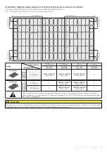
Страница 8: ...00Pa 2400Pa 3600Pa 1600Pa X 622 712 mm 2400Pa 2400Pa 1600Pa 1600Pa 2400Pa 2400Pa 1600Pa 1600Pa 2400Pa 2400Pa 1600Pa 1600Pa X 0 100 mm X 1200Pa 1200Pa 800Pa 800Pa 1600Pa 1600Pa 1066Pa 1066Pa X 100 250...

Страница 9: ...learance Gap Clamping zone 20 40 mm 40 60 mm 60 mm 20 mm Test Load DesignLoad Test Load DesignLoad Test Load DesignLoad Test Load DesignLoad 0 650 mm 1200Pa 1200Pa 800Pa 800Pa 3000Pa 2400Pa 2400Pa 160...

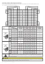
Страница 10: ...600Pa 1600Pa X 0 100 mm X 1200Pa 1200Pa 800Pa 800Pa 1600Pa 1600Pa 1066Pa 1066Pa X 100 250 mm X 800Pa 800Pa 533Pa 533Pa 2400Pa 2400Pa 1600Pa 1600Pa X Rail length under module 100 200 mm Min 100 mm Max...

Страница 11: ...Pa 2800Pa 1600Pa 5400Pa 2400Pa 3600Pa 1600Pa X 340 420 mm 1800Pa 1800Pa 1200Pa 1200Pa 6200Pa 4000Pa 4133Pa 2666Pa 7000Pa 4000Pa 4666Pa 2666Pa X 420 520 mm 1200Pa 1200Pa 800Pa 800Pa 3000Pa 2400Pa 2400P...

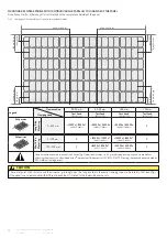
Страница 12: ...m 4 in 250 mm 9 8 in 250 mm 9 8 in 100 mm 4 in 100 mm 4 in 650 mm 25 6 in 0 0 0 0 0 0 650 mm 25 6 in Rail position Rail position Legend Clearance Gap Clamping zone 20 40 mm 40 60 mm 60 mm 20 mm Test L...

Страница 13: ...Pa 1600Pa X 0 100 mm X 1200Pa 1200Pa 800Pa 800Pa 1600Pa 1600Pa 1066Pa 1066Pa X 100 250 mm X 800Pa 800Pa 533Pa 533Pa 2400Pa 2400Pa 1600Pa 1600Pa X Rail length under module 100 200 mm Min 100 mm Max 200...

Страница 14: ...0Pa 1600Pa X 225 357 mm 1800Pa 1800Pa 1200Pa 1200Pa 4200Pa 2400Pa 2800Pa 1600Pa 5400Pa 2400Pa 3600Pa 1600Pa X 357 582 mm 1800Pa 1800Pa 1200Pa 1200Pa 6200Pa 4000Pa 4133Pa 2666Pa 7000Pa 4000Pa 4666Pa 26...

Страница 15: ...ELS WITH CONTINOUS RAILS PARALLEL TO LONG SIDE OF THE PANEL A continous rail or other support structure spans the complete underside of the panel Legend Clearance Gap Clamping zone 20 40 mm 40 60 mm 6...

Страница 16: ...357 582 mm 1200Pa 1200Pa 800Pa 800Pa 3000Pa 3000Pa 2000Pa 2000Pa 4200Pa 4000Pa 2800Pa 2666Pa X 582 622 mm 1200Pa 1200Pa 800Pa 800Pa 2400Pa 2400Pa 1600Pa 1600Pa 3600Pa 2400Pa 2400Pa 1600Pa X 622 712 mm...

Страница 17: ...s apply a safety factor of 1 5 to the stated test load e g test load 5400 Pa 1 5 3600 Pa design load Part Name Material Rail 6105 T5 aluminum extrusion Bolt M6 x 25 drop inT stud kit Nut M6 flanged he...

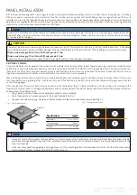
Страница 18: ...d the short side as shown in fig 16 and can be further identified by the grounding symbol stamped in the frame next to it Check all applicable requirements before beginning installation Suitable groun...

Страница 19: ...lestandards e g IEC 62852orUL6703 toensuretheyarefitforpurposeandsafety Useofanychemicalsorlubricantsontheconnectorsorcontactsmayonlybecarriedoutinlinewiththeconnectormanufacturer sinstructions TheREC...

Страница 20: ...to local guidelines and regulations By ensuring REC solar panels are disposed of correctly you will help prevent potential negative impact on the environment and human health The majority of the panel...

Страница 21: ...3 34 7 35 0 NominalPowerCurrent IMPP A 10 62 10 65 10 68 10 72 OpenCircuitVoltage VOC V 40 6 40 8 41 0 41 2 ShortCircuitCurrent ISC A 11 26 11 32 11 38 11 45 PanelEfficiency 19 7 20 0 20 3 20 5 Values...

Страница 22: ...34 3 34 7 NominalPowerCurrent IMPP A 10 60 10 62 10 65 10 68 OpenCircuitVoltage VOC V 40 5 40 6 40 8 41 0 ShortCircuitCurrent ISC A 11 19 11 26 11 32 11 38 PanelEfficiency 19 4 19 7 20 0 20 3 Values...

Страница 23: ...ncy 18 3 18 6 18 9 19 2 19 5 19 8 Values at standard test conditions STC air mass AM 1 5 irradiance 1000 W m temperature 25 C based on a production spread with a toleranceofPMAX VOC ISC 3 withinonewat...

Страница 24: ...10 28 PanelEfficiency 18 3 18 6 18 9 19 2 19 5 Values at standard test conditions STC air mass AM 1 5 irradiance 1000 W m temperature 25 C based on a production spread with a toleranceofPMAX VOC ISC 3...

Страница 25: ...ominalPowerCurrent IMPP A 10 62 10 65 10 68 10 72 OpenCircuitVoltage VOC V 40 8 40 9 41 1 41 3 ShortCircuitCurrent ISC A 11 31 11 36 11 41 11 46 PanelEfficiency 19 7 20 0 20 3 20 5 Values at standard...

Страница 26: ...VMPP V 33 5 33 9 34 3 34 7 NominalPowerCurrent IMPP A 10 60 10 62 10 65 10 68 OpenCircuitVoltage VOC V 40 7 40 8 40 9 41 1 ShortCircuitCurrent ISC A 11 27 11 31 11 36 11 41 PanelEfficiency 19 4 19 7...

Страница 27: ...slack to prevent damage due to water level changes and wave motions ii Mounting panels Installation of REC solar panels must be in accordance with the aforementioned standard mounting instructions Th...

Страница 28: ...MLPE devices may also be attached to the mounting construction In such cases refer to the instructions provided by the manufacturer Wherever possible the installation of the MLPE device should not co...

Страница 29: ...he market of electrical equipment designed for use within certain voltage limits The technical documentation and full compliance with the standards listed below proves the conformity of the product wi...

Страница 30: ...08 2019 E Updated Datasheets 01 2020 F Updated Datasheets 06 2020 G Updated Installation Manual Layout removed REC Peak Energy Series inclusion of REC N Peak Series 09 2020 H Addition of REC TwinPeak...

Страница 31: ...RECSOLARPTE LTD 20TUASSOUTHAVENUE14 SINGAPORE637312 SINGAPORE Tel 6564959228 Mail post recgroup com www recgroup com...

Отзывы: