14
REC Installation Manual - REC Solar Panels - IEC
61215
/
61730
Rev L
-
09
.
21
Ref: PM
-
IM
-20
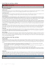
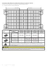
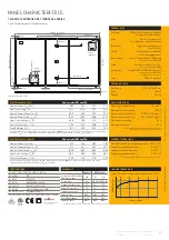
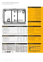
250 mm [9.8 in]
100 mm [3.9 in]
357 mm [14.1 in]
582 mm [22.9 in]
622 mm [24.5 in]
712 mm [28.0 in]
0
0
250 mm [9.8 in]
100 mm [3.9 in]
0
225 mm [8.9 in]
250 mm [9.8 in]
100 mm [3.9 in]
357 mm [14.1 in]
582 mm [22.9 in]
622 mm [24.5 in]
712 mm [28.0 in]
0
0
250 mm [9.8 in]
100 mm [3.9 in
]
0
225 mm [8.9 in]
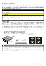
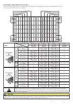
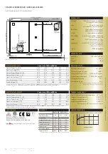
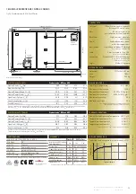
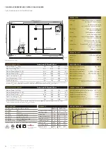
CAUTION
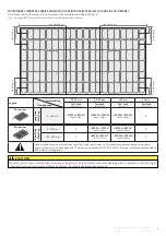
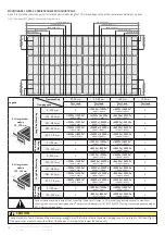
The center point of each clamp and the minimum grip length must be fully located in the same clamping zones to be rated to that load (fig.
9
).
If the panel is secured in zones with di
ff
erent load values, it is rated to the lowest load value only.
Rail positioning
Rail positioning
Fig.
9
: Clamping of REC N-Peak
2
Series panels with rails parallel to short side of the panel
Legend
Clearance Gap
Clamping zone
20-40
mm
40-60
mm
>
60
mm
<
20
mm
Test Load
(Design Load)
Test Load
(Design Load)
Test Load
(Design Load)
Test Load
(Design Load)
0
-
225
mm
X
+
1200
Pa /
-1200
Pa *
(+
800
Pa /
-800
Pa)
+
2400
Pa /
-2400
Pa
(+
1600
Pa /
-1600
Pa)
X
225
-
357
mm
+
1800
Pa /
-1800
Pa *
(+
1200
Pa /
-1200
Pa)
+
4200
Pa /
-2400
Pa
(+
2800
Pa /
-1600
Pa)
+
5400
Pa /
-2400
Pa
(+
3600
Pa /
-1600
Pa)
X
357
-
582
mm
+
1800
Pa /
-1800
Pa *
(+
1200
Pa /
-1200
Pa)
+
6200
Pa /
-4000
Pa
(+
4133
Pa /
-2666
Pa)
+
7000
Pa /
-4000
Pa
(+
4666
Pa /
-2666
Pa)
X
582
-
622
mm
+
1200
Pa /
-1200
Pa *
(+
800
Pa /
-800
Pa)
+
3000
Pa /
-2400
Pa
(+
2400
Pa /
-1600
Pa)
+
5400
Pa /
-2400
Pa
(+
3600
Pa /
-1600
Pa)
X
622
-
712
mm
+
2400
Pa /
-2400
Pa
(+
1600
Pa /
-1600
Pa)
+
2400
Pa /
-2400
Pa
(+
1600
Pa /
-1600
Pa)
+
2400
Pa /
-2400
Pa
(+
1600
Pa /
-1600
Pa)
X
0
-
100
mm
X
+
1200
Pa /
-1200
Pa *
(+
800
Pa /
-800
Pa)
+
1600
Pa /
-1600
Pa *
(+
1066
Pa /
-1066
Pa)
X
100
-
250
mm
X
+
800
Pa /
-800
Pa *
(+
533
Pa /
-533
Pa)
+
2400
Pa /
-2400
Pa
(+
1600
Pa /
-1600
Pa)
X
Once a module is secured in each of the
4
zones (fig.
2
), additional clamps, i.e.,
≥5
, may be freely located on panel frame without
a
ff
ecting the warranty. Loads marked with a
*
were not certified as part of IEC
61215
/
61730
testing; these have been evaluated by
REC’s internal testing process.
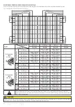
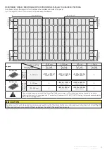
Legend
Clearance Gap
Clamping zone
20-40
mm
40-60
mm
>
60
mm
<
20
mm
Test Load
(Design Load)
Test Load
(Design Load)
Test Load
(Design Load)
Test Load
(Design Load)
0
-
650
mm
+
1200
Pa /
-1200
Pa *
(+
800
Pa /
-800
Pa)
+
3000
Pa /
-2400
Pa
(+
2400
Pa /
-1600
Pa)
+
5400
Pa /
-2400
Pa
(+
3600
Pa /
-1600
Pa)
X
0
-
100
mm
X
+
1200
Pa /
-1200
Pa *
(+
800
Pa /
-800
Pa)
+
1600
Pa /
-1600
Pa *
(+
1066
Pa /
-1066
Pa)
X
100
-
250
mm
X
+
800
Pa /
-800
Pa *
(+
533
Pa /
-533
Pa)
+
2400
Pa /
-2400
Pa
(+
1600
Pa /
-1600
Pa)
X
Once a module is secured in each of the
4
zones (fig.
2
), additional clamps, i.e.,
≥5
, may be freely located on panel frame without
a
ff
ecting the warranty. Loads marked with a
*
were not certified as part of IEC
61215
/
61730
testing; these have been evaluated by
REC’s internal testing process.
Lo
ng
S
id
e
M
ou
nt
in
g
Sh
or
t S
id
e
M
ou
nt
in
g
Rail position
Rail position
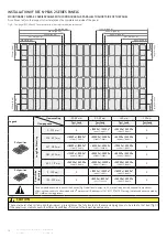
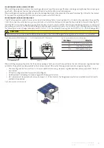
INSTALLATION OF REC N
-
PEAK
2
SERIES PANELS
MOUNTING REC N
-
PEAK
2
SERIES PANELS WITH CONTINOUS RAILS PARALLEL TO SHORT SIDE OF THE PANEL
A continous rail (or other support structure) spans the complete underside of the panel.

