3. Functional Test
The following functional test and set up
procedures must be carried out before sea trials
are attempted.
3.1 Switch on
Switch on the electrical supply from the main
panel. All control units will emit a short beep tone
and display 'ST7000'. Within 2 seconds
Standby
will be displayed to indicate the computer is active
and the autopilot is in Standby mode.
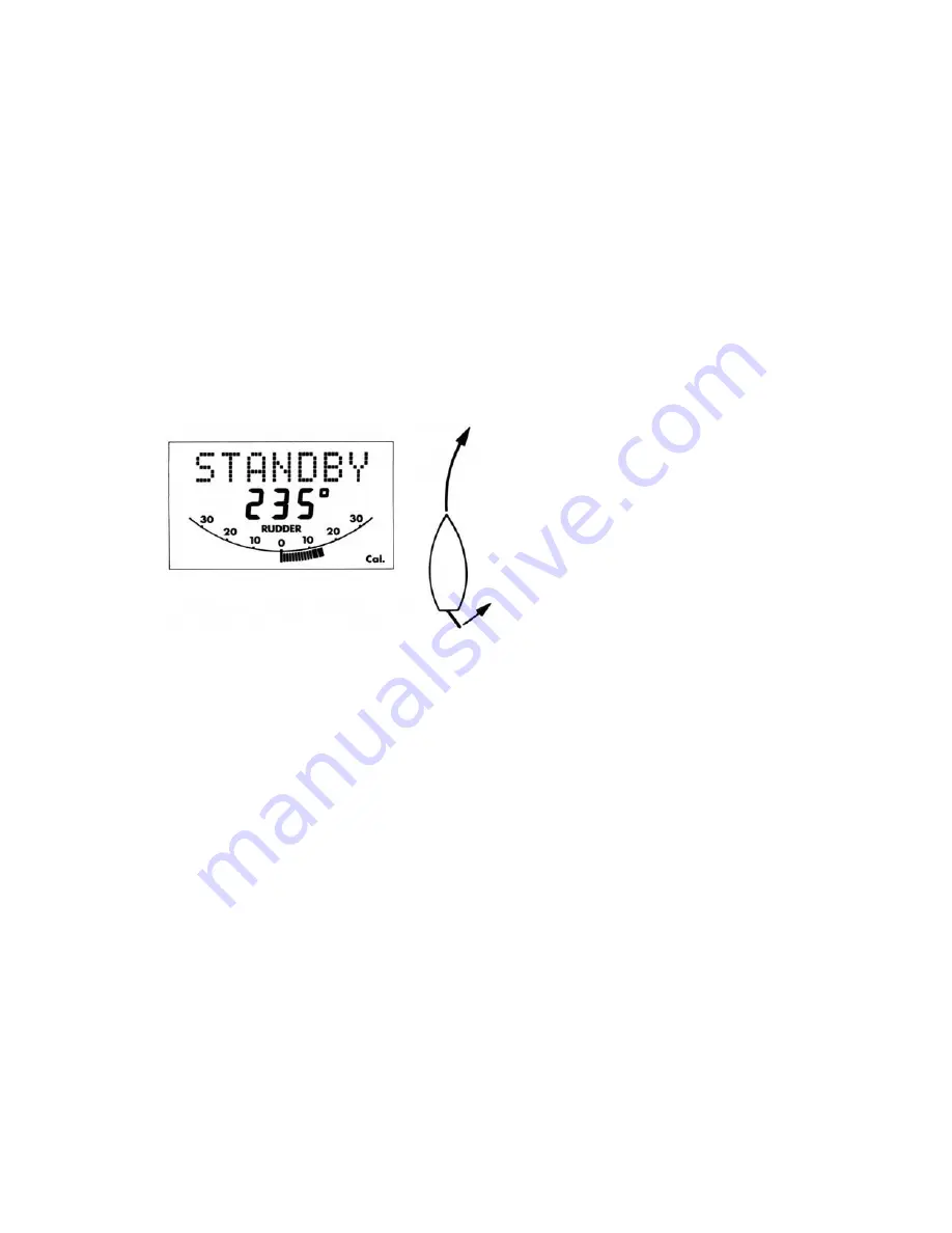
3.2 Rudder Angle Sense
Moving the wheel to produce a turn to starboard
should move the rudder angle display to the right:-
If the display moves in the opposite direction the
red and green wires of the rudder reference
transducer should be reversed.
3.3 Mechanical Test
(Manual Steering)
The steering system and drive unit/rudder
reference unit should be carefully inspected and
the following points checked using the steering
wheel to drive the vessel's steering from hardover
to hardover.
•
The steering system reaches the Rudder End
Stops before the Drive Actuator reaches its
end stops (Linear/Stern Drive).
•
No part of the Autopilot Drive System fouls
any part of the steering system or vessel's
structure through full travel (all drives),
•
The mechanical alignment of the drive unit is
as specified in this manual (Linear/Stern
Drive).
•
The mechanical alignment of the Rudder
Reference Unit is as specified in this manual
(all drives).
•
All connecting wires are secured clear of the
bilge and cannot foul any part of the steering
system. Any connectors are tightly secured
(all drives).
•
All securing bolts are fully tightened and
mechanical locking arrangements as
specified are in place (all drives).
3.4 Rudder Angle Alignment
With the rudder amidships, check that the rudder
angle display reads zero. Any misalignment must
be removed by rotating the rudder reference
transducer within the slots in the body.
3.5 Operating Sense
The operating sense of the autopilot can be
checked as follows:-
•
Push
Auto.
•
Push + 10 which should move the rudder a
few degrees to produce a turn to starboard. If
the rudder moves hardover to port the motor
connections between the course computer
and drive unit should be reversed.
3.6 Rudder Deadband
The factory preset rudder deadband level (see 4-
1) will provide stable rudder positioning on most
steering systems. On some steering systems
where a rotary or hydraulic drive unit is sited a
long way from the rudder, slight instability may
occur. This can be removed by increasing the
'damping' level (see 4.3). Any increase should be
minimised as it will reduce the autopilots course
keeping accuracy.
3.7 Mechanical Test
(Autopilot Steering)
Rotary/Linear/Hydraulic Drives
Warning:
When the steering system is being
moved manually or under drive from the autopilot
do not
touch any part of the system. The forces
exerted are considerable and could cause injury.
•
Push
Auto.
•
Push the + 10 button repeatedly to drive the
rudder hardover onto end stops
(Note:
May
require increasing the rudder limit (see 4.3)).
•
Ensure the drive unit mounting shows no sign
of movement.
32
Содержание ST7000
Страница 1: ...ST7000 Installation...
Страница 2: ...Autohelm Autohelm Autohelm Autohelm...
Страница 3: ......
Страница 5: ...1...
Страница 13: ...8...
Страница 51: ...46...
Страница 52: ...47...
Страница 53: ...44321 5 48...
Страница 54: ......


