Important information
v
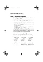
• Ensure that someone is present at the helm AT ALL TIMES, to take manual
control in an emergency.
• Make sure that all members of crew know how to disengage the autopilot.
• Regularly check for other boats and any obstacles to navigation – no matter
how clear the sea may appear, a dangerous situation can develop rapidly.
• Maintain an accurate record of the boat’s position by using either a naviga
tion aid or visual bearings.
• Maintain a continuous plot of your boat’s position on a current chart. Ensure
that the locked autopilot heading will steer the boat clear of all obstacles.
Make proper allowance for tidal set – the autopilot cannot.
• Even when your autopilot is locked onto the desired track using a navigation
aid, always maintain a log and make regular positional plots. Navigation sig
nals can produce significant errors under some circumstances and the autopi
lot will not be able to detect these errors.
EMC installation guidelines
Raymarine equipment and accessories are designed to the best industry
standards for use in the recreational marine environment.
Their design and manufacture conforms to the appropriate Electromagnetic
Compatibility (EMC) regulations, but correct installation is required to ensure that
performance is not compromised.
The guidelines given here describe the conditions for optimum EMC performance,
but it is recognized that it may not be possible to meet all of these conditions in all
situations. To ensure the best possible conditions for EMC performance within the
constraints imposed by any location, always ensure the maximum separation
possible between different items of electrical equipment.
For
optimum
EMC performance, it is recommended that
wherever
possible
:
• Raymarine equipment and the cables connected to it are:
• At least 3 ft (1 m) from any equipment transmitting or cables carrying
radio signals e.g. VHF radios, cables and antennas. In the case of SSB
radios, the distance should be increased to 7 ft (2 m).
• More than 7 ft (2 m) from the path of a radar beam. A radar beam can nor
mally be assumed to spread 20 degrees above and below the radiating
element.
• The product is supplied from a separate battery from that used for engine
start. Power supply voltages below the minimum specified for a product, and
starter motor transients, can cause the product to reset. This will not damage
81282_1.book Page v Monday, October 2, 2006 1:58 PM
Содержание SmartPilot S1 Tiller Pilot
Страница 28: ...16 S1 Wheel and Tiller Pilots Commissioning Guide 81282_1 book Page 16 Monday October 2 2006 1 58 PM ...
Страница 70: ...58 S1 Wheel and Tiller Pilots Commissioning Guide 81282_1 book Page 58 Monday October 2 2006 1 58 PM ...
Страница 74: ...62 S1 Wheel and Tiller Pilots Commissioning Guide 81282_1 book Page 62 Monday October 2 2006 1 58 PM ...


