background image

2.14 System integration

You can add additional features and functions to your G-Series
system by connecting a number of external devices to your
multifunction display via the GPM400 processor module.
The following diagram illustrates the various external devices that
can be connected to your system:

9

WXYZ

8

TUV

7

PQRS

4

GHI

5

JKL

6

MNO

ACTIVE

WPTS
MOB

DATA

MENU

PAGE

.

0

2

ABC

3

DEF

1

CANCEL

STANDBY

DODGE

PILOT

OK

RANGE

OUT

IN

ENTER

T

hermal camera

R

AY

240

1

1.18.0

Weather receiver

External GPS

Personal

Computer

Fishfinder

 DSM 30, 300, or 400

SeaTalk

hs

switch

Instruments

Autopilot

AIS receiver /

transceiver

DSC VHF

G-Series system

Additional

multifunction display(s)

Video / Camera / Satellite TV

D

1

1

6

9

2

_

1

Digital Open Array radar scanner

Digital Radome scanner

or

A variety of protocols are used to transfer data between the various
devices in your networked system. The following table details which
devices may be connected, and the type of connectivity (in terms of
protocols and physical interfaces):

Planning the installation

33

Содержание G-Series system

Страница 1: ...G Series system Installation instructions...

Страница 2: ......

Страница 3: ...mpany names referenced herein are used for identification only and are the property of their respective owners This product is protected by patents design patents patents pending or design patents pen...

Страница 4: ......

Страница 5: ...Dual nav station single processor example 24 2 9 Single nav station dual processor example 26 2 10 Dual nav station dual processor example 28 2 11 Entertainment system example 30 2 12 System limits 3...

Страница 6: ...hecks 105 7 1 Language selection 106 7 2 Compass setup 106 7 3 Compass bar 107 7 4 GPS check 108 7 5 GPS setup 108 7 6 Radar check 109 7 7 Sonar check 111 7 8 Setting up Autopilot AIS and Navtex 112 7...

Страница 7: ...152 10 6 Glass bridge monitor 155 Chapter 11 Options and accessories 159 11 1 SeaTalk accessories 160 11 2 SeaTalkng accessories 160 11 3 SeaTalkhs accessories 161 11 4 Monitor accessories 163 11 5 N...

Страница 8: ...8 G Series installation instructions...

Страница 9: ...n accordance with the instructions in this guide Warning Switch off power supply Ensure the boat s power supply is switched OFF before starting to install this product Do NOT connect or disconnect equ...

Страница 10: ...aning When cleaning this product Do NOT wipe the display screen with a dry cloth as this could scratch the screen coating Do NOT use abrasive or acid or ammonia based products Do NOT use a jet wash TF...

Страница 11: ...ors in chart data or information utilized by the product and supplied by third parties Chart cards and memory cards Compatible cards The following types of memory or chart card are compatible with you...

Страница 12: ...on or maintenance it must be replaced in the original position before the product is used Use only ferrites of the correct type supplied by Raymarine authorized dealers Connections to other equipment...

Страница 13: ...ot covered by International Maritime Organization IMO and Safety of Life at Sea SOLAS Carriage Regulations Technical accuracy To the best of our knowledge the information in this document was correct...

Страница 14: ...14 G Series installation instructions...

Страница 15: ...system example on page 22 2 8 Dual nav station single processor example on page 24 2 9 Single nav station dual processor example on page 26 2 10 Dual nav station dual processor example on page 28 2 1...

Страница 16: ...ries system installation and commissioning instructions 87070 G Series system operating instructions quick reference 86126 G Series system user reference handbook 81276 Glass Bridge monitors user guid...

Страница 17: ...ematic templates to record the details of the installation This document includes a number of schematic templates to assist you in planning Nav Stations cables and connections It is important to recor...

Страница 18: ...n your system but can only control 1 monitor at a time You can select which monitor you want to control from the keyboard When a keyboard is associated with a monitor this provides full control of the...

Страница 19: ...e 2 Nav Station 2 bridge 3 Below decks components for example GPM processor unit GVM video module Refer to the installation instructions for information on planning and configuring the Nav Station s f...

Страница 20: ...N ENTER 9 WXY Z 8 TUV 7 PQRS 4 GHI 5 JK L 6 MNO ACTIVE WPTS MOB DAT A MENU PAGE 0 2 ABC 3 DEF 1 CANCEL ST ANDBY DODGE PIL OT OK RANGE OUT IN ENTER 4 1 ENTER CANCEL MENU ENTER CANCEL MENU 12 13 SeaT al...

Страница 21: ...Nav Station 2 for example bridge 5 GPM processor unit 6 SeaTalkng instrument pilot 7 SeaTalk instrument pilot 8 GPS receiver 9 Alarm sounder 10 Digital Sounder Module DSM sonar 11 Radar scanner 12 E S...

Страница 22: ...91 1 DVI VGA SeaT alkhs SeaT alkhs SeaT alkhs SeaT alkhs SeaT alkhs SeaT alkng 9 WXY Z 8 TUV 7 PQRS 4 GHI 5 JK L 6 MNO ACTIVE WPTS MOB DAT A MENU PAGE 0 2 ABC 3 DEF 1 CANCEL ST ANDBY DODGE PIL OT OK R...

Страница 23: ...ilot 6 SeaTalkng instrument 7 Radar scanner 8 Digital Sounder Module DSM sonar 9 Transducer 10 SeaTalkhs switch 11 GPM processor unit 12 Audio output to vessel s audio system 13 SeaTalk alarm output 1...

Страница 24: ...HI 5 JK L 6 MNO ACTIVE WPTS MOB DAT A MENU PAGE 0 2 ABC 3 DEF 1 CANCEL ST ANDBY DODGE PIL OT OK RANGE OUT IN ENTER ENTER CANCEL MENU ENTER CANCEL MENU C lines for plugs sockets DVI VGA DVI VGA DVI VGA...

Страница 25: ...5 Wireless keyboard 6 Wireless keyboard charger point 7 SeaTalkng backbone 8 Wireless base station 9 SeaTalkng pilot 10 SeaTalkng instrument 11 Radar scanner 12 Digital Sounder Module DSM sonar 13 Tra...

Страница 26: ...ABC 3 DEF 1 CANCEL ST ANDBY DODGE PIL OT OK RANGE OUT IN ENTER ENTER CANCEL MENU ENTER CANCEL MENU D11793 1 S Video A V DVI VGA DVI VGA SeaT alkhs SeaT alkhs SeaTalkhs SeaT alk hs SeaT alk hs SeaT al...

Страница 27: ...4 SeaTalkng backbone 5 SeaTalkng instrument 6 Radar scanner 7 Digital Sounder Module DSM sonar 8 Video camera 9 GVM video module 10 GPM processor unit data master 11 SeaTalkhs switch 12 GPM processor...

Страница 28: ...XY Z 8 TUV 7 PQRS 4 GHI 5 JK L 6 MNO ACTIVE WPTS MOB DAT A MENU PAGE 0 2 ABC 3 DEF 1 CANCEL ST ANDBY DODGE PIL OT OK RANGE OUT IN ENTER 4 4 D11794 1 DVI VGA DVI VGA DVI VGA DVI VGA DVI VGA SeaT alkhs...

Страница 29: ...ireless keyboard 5 Nav Station 2 6 Connection to other SeaTalkng devices 7 Wireless base station 8 SeaTalkng backbone 9 GPM processor unit data master 10 SeaTalkhs switch 11 Connection to other SeaTal...

Страница 30: ...HI 5 JK L 6 MNO ACTIVE WPTS MOB DAT A MENU PAGE 0 2 ABC 3 DEF 1 CANCEL ST ANDBY DODGE PIL OT OK RANGE OUT IN ENTER 1 3 5 10 D11795 1 S Video A V A V SeaTalkhs SeaTalkhs SeaT alkng SeaTalk ng SeaT alk...

Страница 31: ...ss keyboard 4 Satellite TV 5 Wireless base station 6 Video camera 7 Video camera with audio connection 8 GVM video module 9 SeaTalkhs switch 10 GPM processor unit 11 Audio output to vessel s audio sys...

Страница 32: ...of the installation and commissioning process it must be done as part of the initial setup The data master handles all the data from the various marine electronics installed around your vessel The dat...

Страница 33: ...T OK RANGE OUT IN ENTER Thermalcamera RA Y 240 11 18 0 Weather receiver ExternalGPS Personal Computer Fishfinder DSM30 300 or 400 SeaT alkhs switch Instruments Autopilot AIS receiver transceiver DSC V...

Страница 34: ...tion SeaTalkhs Device Type Suitable Devices Connectivity of ONE of the following Raymarine fishfinders DSM 30 DSM 300 DSM 400 Cartography included Embedded internal Navionics cartography GPM400 intern...

Страница 35: ...SeaTalkng or NMEA 0183 Autopilot Raymarine All current Raymarine autopilots SeaTalk SeaTalkng Autopilot third party Third party autopilots NMEA 0183 waypoint and bearing information VHF radio Raymari...

Страница 36: ...using the optional adaptor cable Thermal camera The G Series system supports the connection of ONE of the following Raymarine thermal cameras T300 thermal camera 9 Hz T303 thermal camera 30 Hz T350 th...

Страница 37: ...must NOT be connected to SeaTalkng when part of a G Series network E Series Widescreen displays must NOT be connected to SeaTalk when part of a G Series network Master slave operation When using an E...

Страница 38: ...Widescreen display in a G Series system can operate 1 scanner at any one time To use the second scanner you must select it in the Radar application s Setup Menu This does not automatically power down...

Страница 39: ...nstruments and displays to share information and so improve the functionality of the system These connections may be made using a number of different protocols Fast and accurate data collection and tr...

Страница 40: ...itional instruments and functions can be added to a SeaTalk system simply by plugging them into the network SeaTalk equipment can also communicate with other non SeaTalk equipment via the NMEA 0183 st...

Страница 41: ...pical power distribution on page 45 3 5 Power cables on page 47 3 6 SeaTalkhs network on page 48 3 7 SeaTalkng connection on page 65 3 8 SeaTalk connection on page 67 3 9 NMEA 0183 connection on page...

Страница 42: ...ead or deckhead use a suitable watertight feed through Do NOT run cables near to engines or fluorescent lights Always route data cables as far away as possible from other equipment and cables high cur...

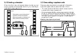
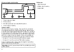
Страница 43: ...necessary protection 3 3 Grounding requirements These grounding requirements are applicable for Raymarine equipment supplied with a separate drain wire or screen The product power cable drain conducto...

Страница 44: ...minimum requirement for the path to ground bonded or non bonded is via a flat tinned copper braid with a 30 A rating 1 4 inch or greater If this is not possible an equivalent stranded wire conductor...

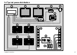
Страница 45: ...3 4 Typical power distribution 3 2 1 2 4 5 6 7 10 8 9 11 11 11 11 D11803 1 3 Cables and connections 45...

Страница 46: ...ion panel as the monitors If in doubt the monitors or affected equipment can be wired directly back to the battery power source via a dedicated breaker Refer to the separate monitor documentation for...

Страница 47: ...5 m 32 8 to 49 2 ft 24 volts 16 1 31 12 volts 12 3 31 15 to 20 m 49 2 to 65 6 ft 24 volts 14 2 08 GVM400 video module Power cables GVM video module power cable requirements The GVM video module is not...

Страница 48: ...Digital radar Digital Sounder Module DSM sonar GVM video module Monitors SR100 Sirius weather audio receiver Additional multifunction displays for example E Series Widescreen PC or laptop using RayTe...

Страница 49: ...E06055 10 m 32 8 ft SeaTalkhs patch cable E06056 15 m 49 2 ft SeaTalkhs patch cable A62136 20 m 65 6 ft SeaTalkhs patch cable E06057 Monitor connection Connect the G Series monitors to both the GPM p...

Страница 50: ...eft in place IP selector switch The IP selector switch at the rear of the monitor must be in the UP position Screen resolution and aspect ratio G Series monitor screen resolution and aspect ratio Each...

Страница 51: ...ced connection This is to avoid 0 V loops which can cause interference issues Wired keyboard connections Wired keyboards are connected to the G Series system using the SeaTalkng backbone D11814 1 9 WX...

Страница 52: ...nt NOT both Wireless keyboard connections Wireless keyboards connect to the G Series system via the wireless base station A charge point is also required for the wireless keyboard D11816 1 9 WXY Z 8 T...

Страница 53: ...one The charge point must also be connected to the SeaTalkng backbone The charge point is typically fitted to your vessel s bulkhead D11817 1 1 2 3 4 5 6 2 7 1 SeaTalkng backbone 2 SeaTalkng spur 3 Se...

Страница 54: ...s 400 mm 15 75 in SeaTalkng spur cable A06038 1 m 3 3 ft SeaTalkng spur cable A06039 Supplied with the keyboard 3 m 9 8 ft SeaTalkng spur cable A06040 5 m 16 4 ft SeaTalkng spur cable A06041 Wireless...

Страница 55: ...video sources connected to the S Video Composite 4 inputs If an audio connection is made to the GVM video module the audio is sent to the GPM processor unit The GPM processor unit features an audio o...

Страница 56: ...GVM video module connections D11820 1 SeaT alkhs 1 3 7 4 2 8 6 5 56 G Series installation instructions...

Страница 57: ...input If a thermal camera is connected to a GVM video module no further video devices may be connected to that GVM unit The G Series system supports a maximum of 3 GVM video modules providing a total...

Страница 58: ...upplied with the GPM processor unit 15 m 49 2 ft stereo audio cable R08298 Digital radar connection Digital radar scanners connect to the G Series system via the SeaTalkhs switch using a dedicated pow...

Страница 59: ...en array radar scanner connection D11825 1 1 2 3 4 5 1 Digital open array radar scanner 2 GPM processor unit 3 SeaTalkhs switch 4 VCM100 power converter 5 Power and data digital cable Cables and conne...

Страница 60: ...en this cable and the system For non networked systems a crossover coupler is required for directly connecting the radar scanner These connections are NOT shown in the diagram above Note For Digital O...

Страница 61: ...15 m 49 2 ft Power and data digital cable A55078D 25 m 82 0 ft Power and data digital cable A55079D Note The maximum length for the radar power and data digital cable including any extensions is 25 m...

Страница 62: ...1 DSM module SeaTalkhs network cables Cable Part number 1 5 m 4 9 ft SeaTalkhs network cable E55049 5 m 16 4 ft SeaTalkhs network cable E55050 10 m 32 8 ft SeaTalkhs network cable E55051 20 m 65 6 ft...

Страница 63: ...hat input only and does NOT support the connection of any further video devices Each thermal camera must be connected to Video Input 1 of a GVM video module Dual payload thermal cameras include 2 inde...

Страница 64: ...Unit JCU An Ethernet with power cable is used to connect the JCU The JCU is supplied with a 1 5 m 5 ft Ethernet cable for this connection if you require a different length contact your dealer for suit...

Страница 65: ...pilots e g ST70 with SmartPilot SPX course computer G Series keyboard all variants Typical SeaTalkng system D11830 1 ENTER CANCEL MENU ENTER CANCEL MENU Power Supply 9 WXY Z 8 TUV 7 PQRS 4 GHI 5 JK L...

Страница 66: ...is incorrectly terminated SeaTalkng cabling SeaTalkng cables Connection Cable Notes Backbone cables various lengths The main cable carrying data Spurs from the backbone are used to connect SeaTalkng d...

Страница 67: ...or the chart application SeaTalk and alarm connection The alarm output and SeaTalk are combined into a single connector which includes a 12 volt fused power supply The wiring method for the alarm depe...

Страница 68: ...he SeaTalk bus must be connected to the master GPM processor unit You can connect the SeaTalk bus to other GPMs for redundancy purposes if required In the event that the master GPM fails the other GPM...

Страница 69: ...sharing the following types of data Fastheading from an autopilot or fastheading sensor This is required for radar target acquisition MARPA AIS information from an AIS receiver or transceiver This is...

Страница 70: ...IN Refer to NMEA device handbook 9 GPM negative OUT Brown 4 10 NMEA device negative IN Refer to NMEA device handbook 11 Screen not connected 5 12 NMEA device Multiple NMEA devices You may connect NME...

Страница 71: ...on Raymarine cables must use a shielded twisted pair cable to minimise interference 3 10 NMEA 2000 connection The system can receive data from NMEA 2000 devices for example data from compatible engine...

Страница 72: ...adaptor cable female A06045 1 5 m 4 9 ft SeaTalkng to DeviceNet adaptor cable male A06046 3 11 GPS connection Depending upon your GPS type it may be either connected via SeaTalk or NMEA 0183 See also...

Страница 73: ...NMEA 0183 Connection using SeaTalkng D11834 1 SeaT alkng AIS 500 1 2 1 GPM processor unit 2 AIS500 transceiver Connection using NMEA 0183 D11835 1 NM EA0183 38400 VHF NM EA0183 4800 1 2 3 4 1 VHF ante...

Страница 74: ...eading sensor If your system includes a Raymarine SPX course computer connected using SeaTalkng then you will not need the separate Fastheading connection Typical Fastheading from NMEA 0183 compatible...

Страница 75: ...tion source on page 76 4 2 GPM processor unit on page 76 4 3 G Series monitors on page 79 4 4 G Series keyboard on page 80 4 5 Command center keyboard wireless upgrade on page 87 4 6 GVM400 video modu...

Страница 76: ...ration for example an engine Install below decks in a dry area The unit is NOT designed for use in a sealed enclosure Access to the unit is required for software and chart updates Must be mounted on a...

Страница 77: ...ding End User License Agreement EULA Installation and commissioning instructions User reference Quick reference Cutting template 3 1 5 m 4 9 ft power cable 4 1 5 m 4 9 ft NMEA cable 5 1 m 3 3 ft SeaTa...

Страница 78: ...ing clearances Allow the following clearances from other equipment and surfaces Side Distance Top 100 mm 3 94 in Left 100 mm 3 94 in Right 100 mm 3 94 in Bottom Enough to allow cable entry Front 150 m...

Страница 79: ...ame G Series G120 G150 G170 G190 81277 Raymarine Sunlight Viewable Marine Displays User s Guide G Series Glass Bridge GB150 GB170 81324 Glass Bridge Monitors User s Guide Parts supplied D11801 1 6 1 2...

Страница 80: ...d The Command Center keyboard NOT Compact variant can be installed for 2 different types of use Wired operation flush mounted Wireless operation using the wireless upgrade kit and SeaTalkng base stati...

Страница 81: ...el seal 4 Rear clamp assembly 5 Installation instructions 6 400 mm 15 75 in SeaTalkng backbone cable 7 1 m 3 3 ft SeaTalkng NMEA2000 spur cable 8 Finger nut quantity 4 9 Stud quantity 4 10 SeaTalkng T...

Страница 82: ...D11399 1 97 5 mm 3 84 in 24 mm 0 95 in 29 mm 1 14 in 163 mm 6 4 in 53 mm 2 08 in 82 G Series installation instructions...

Страница 83: ...unting arrangement D11873 1 1 2 3 4 5 6 7 1 Sun cover 2 Keyboard 3 Panel seal adhesive side up 4 SeaTalkng cable 5 Rear clamp assembly 6 Finger nut quantity 4 7 Stud quantity 4 Location and mounting 8...

Страница 84: ...yboard 4 Panel seal 5 Rear clamp assembly 6 SeaTalkng T piece connector 7 Screw pack containing Finger nut quantity 4 Stud quantity 4 8 400 mm 15 75 in SeaTalkng backbone cable 9 1 m 3 3 ft SeaTalkng...

Страница 85: ...D11871 1 297 mm 11 69 in 98 mm 3 85 in 35 mm 1 38 in 59 8 mm 2 35 in 46 mm 1 81 in Location and mounting 85...

Страница 86: ...arrangement D11872 1 1 2 3 4 5 7 6 1 Sun cover 2 Keyboard 3 Panel seal adhesive side up 4 SeaTalkng cable 5 Rear clamp assembly 6 Finger nut quantity 4 7 Stud quantity 4 86 G Series installation inst...

Страница 87: ...tion requirements When selecting a location for the keyboard wireless base station it is important to consider a number of factors You must perform a site survey to find an appropriate location and en...

Страница 88: ...e station 2 Installation instructions 3 SeaTalkng T piece connector 4 400 mm 15 75 in SeaTalkng backbone cable 5 1 m 3 3 ft SeaTalkng spur cable stripped ends Dimensions D11880 1 66 mm 2 6 in 117 mm 4...

Страница 89: ...nitors so that you can operate the system while the keyboard is charging Connect cable into keyboard before clamping in place Parts supplied D1 1799 1 1 2 3 4 6 5 7 8 1 Connector cover 2 Battery pack...

Страница 90: ...pping screws quantity 3 4 Mounting plate Ensure flat edge is located to left side for correct orientation 5 Gasket Ensure protective cover is removed from each side of gasket 6 Washer 7 Charge plug 8...

Страница 91: ...Wireless keyboard charging The keyboard must be charged before first use To charge the keyboard connect it to the charge point and place it in the cradle The keyboard must be charged for at least 6 ho...

Страница 92: ...install near sources of heat or vibration for example an engine Install below decks in a dry area Must be mounted on a vertical surface Sides and top must be level Parts supplied D1 1797 1 3 4 1 2 1 G...

Страница 93: ...Dimensions D11883 1 170 mm 6 7 in 237 mm 9 33 in 56 mm 2 2 in Mounting arrangement Location and mounting 93...

Страница 94: ...Do NOT install near sources of heat or vibration for example an engine Mount below decks in a dry area Install on a vertical surface Parts supplied D11802 1 1 1 Alarm buzzer Dimensions D11885 1 38 mm...

Страница 95: ...Chapter 5 Initial power on test Chapter contents 5 1 Before powering up on page 96 5 2 Power up test on page 96 Initial power on test 95...

Страница 96: ...he equipment at the distribution panel 1 Monitors and ancillary equipment 2 GPM processor units Power up sequence Power up the monitors first to allow the boot sequence and start up information to be...

Страница 97: ...checks Check that each GPM unit is correctly connected by looking at its status LED found next to the SeaTalk alarm output On a healthy GPM unit the LED will flash green For a full LED status listing...

Страница 98: ...98 G Series installation instructions...

Страница 99: ...101 6 3 First time configuration on page 101 6 4 Designating the data master master GPM on page 102 6 5 Creating a nav station on page 102 6 6 Assigning a monitor to a nav station on page 103 6 7 Assi...

Страница 100: ...10547 2 9 WXY Z 8 TUV 7 PQRS 4 GHI 5 JK L 6 MNO ACTIVE WPTS MOB DAT A MENU PAGE 0 2 ABC 3 DEF 1 CANCEL OK RANGE OUT IN ENTER ST ANDBY DODGE PIL OT 2 1 3 4 5 6 1 Power key 2 Monitor select OSD On Scree...

Страница 101: ...First time configuration When you set up the system for the first time an automatic menu sequence is launched to help you configure your Nav Stations This sequence is launched for systems that do not...

Страница 102: ...S MASTER softkey Note If you are unsure of which GPM to select use the DISCOVER GPM softkey which shows a message on every monitor identifying the GPM to which it is connected 6 5 Creating a nav stati...

Страница 103: ...as follows Information Description Monitor type Name Specify a unique name for the monitor All GPM Select the GPM that the monitor is connected to Use the DISCOVER GPM softkey to determine the current...

Страница 104: ...TO NAVSTATION softkey 7 Select the appropriate Nav Station 6 8 Assigning a keyboard to an individual monitor 1 Press the MENU button 2 Select System Setup 3 Select System Configuration 4 Select Assign...

Страница 105: ...age 107 7 4 GPS check on page 108 7 5 GPS setup on page 108 7 6 Radar check on page 109 7 7 Sonar check on page 111 7 8 Setting up Autopilot AIS and Navtex on page 112 7 9 Thermal camera setup and che...

Страница 106: ...s setup You may need to linearize or swing a connected compass to achieve optimal accuracy Linearizing or swinging your compass involves a calibration procedure to fine tune the heading alignment Note...

Страница 107: ...arker is GREEN When you use the compass bar with an active waypoint the bearing marker is BLUE and the active waypoint symbol indicates the bearing to your waypoint The default compass bar mode is hea...

Страница 108: ...chart indicates that neither heading nor Course Over Ground COG data is available 7 5 GPS setup The GPS setup options enable you to configure a connected GPS receiver The Global Positioning System GPS...

Страница 109: ...plication In order for your GPS receiver and multifunction display to correlate accurately with your paper charts they must be using the same datum Refer to the Using the Chart chapter for more inform...

Страница 110: ...t bearing alignment Bearing alignment The radar bearing alignment ensures that radar objects appear at the correct bearing relative to your boat s bow You should check the bearing alignment for any ne...

Страница 111: ...er is initialized standby mode 1 Press the RADAR SETUP SCANNER SETUP 2 Select the PARKING OFFSET option then adjust the offset angle required to park the radar so that the antenna comes to rest facing...

Страница 112: ...uld be Enabled if you wish to control a compatible autopilot using the display iii NMEA port settings These should be set appropriately for the connected devices iv Bridge NMEA heading This should be...

Страница 113: ...3 Select the Select GVM menu item A list of all connected GVM video modules is displayed along with serial numbers 4 Select the GVM video module that the thermal camera is connected to 5 Repeat Steps...

Страница 114: ...lifier is switched on and the appropriate input selected Check the video and audio output You will need to Select the Video application from the home screen Set up the video inputs Selecting video sou...

Страница 115: ...6 Select the Auto 4 3 or 16 9 option as appropriate Changing video orientation In the video application 1 Select the PRESENTATION softkey 2 Use the ORIENTATION softkey to select the appropriate option...

Страница 116: ...is data can include any transducer or internally calculated navigation data that is available on NMEA or SeaTalk Additional data includes a compass rose a distance log and four resettable trip counter...

Страница 117: ...fe Depth Minimum Safe Beam Minimum Safe Height Position Mode Determines how positioning data is displayed as Latitude Longitude coordinates or Loran TDs Lat Long default TDs TD Setup When the Position...

Страница 118: ...ption then specify the value using the Manual Variation setting see below Auto compensation value displayed in brackets default Manual Manual Variation When the Variation Source menu item is set to Ma...

Страница 119: ...waypoints routes and tracks will be deleted from any additional multifunction displays Note If this reset function is performed on a G Series system it will also delete your Nav Station settings Facto...

Страница 120: ...t the system displays the units in Feet If the Distance unit is set to Kilometers the system displays the units in Meters Distance Units Nautical Miles default Statute Miles Kilometers Speed Units Kno...

Страница 121: ...play If set to OFF the alarms will NOT be displayed on your multifunction display Preferred GPS Source Your multifunction display supports GPS receivers connected by SeaTalk1 SeaTalkng or NMEA2000 Sel...

Страница 122: ...ble the individual NMEA output sentences for each NMEA port NMEA Port Setting Allows you to specify the appropriate port speed for the equipment connected to each NMEA port When the Navtex 4800 or Nav...

Страница 123: ...800 default Navtex 4800 Navtex 9600 AIS 38400 Waypoint Password Setup This menu allows you to enable password protection for waypoints and to change the password Enable Password OFF default ON Change...

Страница 124: ...124 G Series installation instructions...

Страница 125: ...ng on page 131 8 6 GPS troubleshooting on page 132 8 7 Sonar troubleshooting on page 133 8 8 Thermal camera troubleshooting on page 134 8 9 System data troubleshooting on page 137 8 10 Video troublesh...

Страница 126: ...subjected to comprehensive test and quality assurance programs However if you experience problems with the operation of your G Series multifunction display this section will help you to diagnose and c...

Страница 127: ...e causes Possible solutions Check relevant fuses and breakers Check that the power supply cable is sound and that all connections are tight and free from corrosion The system or part of it does not st...

Страница 128: ...ge monitor with a cable from the GPM connected to an input other than DVI1 Ensure that the cable from the GPM400 is connected to DVI1 on the rear of the monitor A faulty connection to the GPM400 proce...

Страница 129: ...and associated GPM400 are both connected the SeaTalkhs switch The monitor is not a Raymarine G Series marine monitor Only G Series marine monitors are compatible with the SeaTalkhs network required f...

Страница 130: ...ections to SeaTalkng wireless base station Keyboard LCD shows software version message for example 86 78 F64D V0 6A Monitor may also show no keyboards connected message Wireless base station is out of...

Страница 131: ...upler as applicable Check the status of the SeaTalkhs switch SeaTalkhs network problem Check that SeaTalkhs cables are free from damage Software mismatch between equipment may prevent communication Co...

Страница 132: ...ction fault Ensure that GPS connections and cabling are correct and fault free External GPS antenna in poor position For example Below decks Close proximity to transmitting equipment such as VHF radio...

Страница 133: ...switch if applicable SeaTalkhs network problem Check that SeaTalkhs cables are free from damage No data source for the fishfinder Software mismatch between equipment may prevent communication Contact...

Страница 134: ...at the video is connected into video input 1 at the multifunction display or GVM Ensure that the correct video input is selected at the display Video not displayed Problem with power supply to the cam...

Страница 135: ...ate the possibility of a more fundamental camera fault Camera is not a dual payload model Only dual payload dual lens thermal cameras support VIS IR switching Cannot switch between thermal and visible...

Страница 136: ...vironment may benefit from a different Scene Mode setting For example a very cold background such as the sky could cause the camera to use a wider temperature range than appropriate Use the SCENE butt...

Страница 137: ...ument or engine interface Check the power to the SeaTalk bus Data source e g ST70 instrument or engine interface is not operating Refer to the manufacturer s handbook for the equipment in question Ins...

Страница 138: ...onnected to the SeaTalkhs switch Check the status of the SeaTalkhs switch SeaTalkhs network problem Check that SeaTalkhs cables are free from damage Video picture is unavailable at some or all Nav Sta...

Страница 139: ...LED state Possible causes 1 flashing 500 500 ms green LED Normal operation Heartbeat 1 flashing 750 250 ms green LED Standby mode Off for 2 minutes Startup Off for 2 minutes No power 1 steady amber L...

Страница 140: ...ing amber LED Data acquisition failure 2 flashing amber LEDs No network cable unplugged 3 flashing amber LEDs Other network error Flashing 750 250 ms LEDs alternating between amber and red Retrieving...

Страница 141: ...er 2 flashing amber LEDs No network cable unplugged 3 flashing amber LEDs Overheating warning 8 flashing amber LEDs Watchdog restart Flashing 750 250 ms LEDs alternating between amber and red Retrievi...

Страница 142: ...142 G Series installation instructions...

Страница 143: ...Chapter 9 Technical support Chapter contents 9 1 Raymarine customer support on page 144 9 2 3rd party support on page 145 Technical support 143...

Страница 144: ...ts Telephone and email support In the USA Tel 1 603 881 5200 extension 2444 Email Raymarine custhelp com In the UK Europe the Middle East or Far East Tel 44 0 23 9271 4713 Email ukproduct support raym...

Страница 145: ...Contact and support details for 3rd party suppliers can be found on the appropriate websites Navionics www navionics com Sirius marine weather www sirius com marineweather Sirius audio www sirius com...

Страница 146: ...146 G Series installation instructions...

Страница 147: ...tents 10 1 GPM processor unit on page 148 10 2 GVM400 video module on page 149 10 3 Command center keyboard on page 150 10 4 Compact keyboard on page 151 10 5 Monitors on page 152 10 6 Glass bridge mo...

Страница 148: ...5 A at 24 V With external loads 5 A at 12 V 2 5 A at 24 V Environmental Installation environment Operating temperature 15 C to 55 C 5 F to 131 F Non operating temperature 25 C to 70 C 13 F to 158 F R...

Страница 149: ...Nominal supply voltage 12 or 24 V dc Operating voltage range 10 7 to 32 V dc Fuse Breakers 12 V supply 2 A fuse protection at distribution panel 1 2 A thermal circuit breaker protection at distributio...

Страница 150: ...amended by 92 31 EEC EN60945 2002 10 3 Command center keyboard Technical specification Nominal supply voltage 12 V dc from SeaTalkng bus Operating voltage range 9 to 16 V dc Typical power consumption...

Страница 151: ...range 10 to 16 V dc Typical power consumption 150 mA Environmental Installation environment Operating temperature 15 C to 55 C 5 F to 131 F Non operating temperature 25 C to 70 C 13 F to 158 F Relati...

Страница 152: ...el aspect ratio 4 3 Panel sizes G120 12 G150 15 G170 17 G190 19 Native resolution G120 G150 1024 x 768 pixels XGA G170 G190 1280 x 1024 pixels SXGA Brightness G120 1200 cd m2 G150 1200 cd m2 G170 1300...

Страница 153: ...cture In Picture Picture in Picture Child Split Wide Display resolutions and refresh rate VGA 640x480 60 72 75 85 Hz SVGA 800x600 56 60 72 75 85 Hz XGA 1024x768 60 70 75 85 Hz SXGA 1280x1024 60 75 85...

Страница 154: ...0 7 3 kg 16 lb D11893 1 G120 G150 330 mm 13 00 A 380 mm 14 97 284 mm 11 18 B 315 mm 12 39 307 mm 12 08 C 357 mm 14 07 257 mm 10 10 D 292 mm 11 5 118 mm 4 64 118 mm 4 64 E G170 415 mm 16 34 G190 454 mm...

Страница 155: ...50 1024 x 768 pixels GB170 1280 x 1024 pixels Brightness GB150 1500 cd m2 GB170 1100 cd m2 Contrast ratio GB150 700 1 GB150 700 1 Color display 24bit color 16 7 M colors Viewing angle Horizontal 160 8...

Страница 156: ...nput NTSC PAL SECAM Data connections 3 x VGA 15 pin D Sub 2 x DVI DVI D 1 x S Video 4 pin mini DIN 3 x CVBS BNC 1 x SeaTalkhs RJ 45 Power Nominal supply voltage 12 or 24 V dc Operating voltage range 1...

Страница 157: ...3 90 264 0 mm 10 39 305 6 mm 12 03 E 335 0 mm 13 19 367 3 mm 14 46 F Environmental Environmental Operating temperature 10 C to 50 C 14 F to 122 F Relative humidity max 95 Water proof to IPX6 Rating ap...

Страница 158: ...158 G Series installation instructions...

Страница 159: ...2 SeaTalkng accessories on page 160 11 3 SeaTalkhs accessories on page 161 11 4 Monitor accessories on page 163 11 5 NMEA 2000 accessories on page 163 11 6 NMEA 0183 accessories on page 164 11 7 Audio...

Страница 160: ...8 11 2 SeaTalkng accessories SeaTalkng cables and accessories for use with compatible products Description Part No Notes Backbone Kit A25062 Includes 2 x 5 m 16 4 ft Backbone cable 1 x 20 m 65 6 ft Ba...

Страница 161: ...ain the wires for a scanner s power and data connections Cable Part number 5 m 16 4 ft Power and data digital cable A55076D 10 m 32 8 ft Power and data digital cable A55077D 15 m 49 2 ft Power and dat...

Страница 162: ...SeaTalkhs patch cable E06056 15 m 49 2 ft SeaTalkhs patch cable A62136 20 m 65 6 ft SeaTalkhs patch cable E06057 Fully waterproof SeaTalkhs network cables Connect directly from display to display Cabl...

Страница 163: ...ble E06022 500 mm 19 69 in DVI to VGA analogue cable E06053 1 5 m 4 9 ft VGA to VGA cable R08130 5 m 16 4 ft VGA to VGA cable R08174 10 m 32 8 ft VGA to VGA cable R08296 20 m VGA to VGA cable R08297 1...

Страница 164: ...ble R08004 11 7 Audio and video accessories Audio video cables The following cables are available as accessories Cable Part number Notes 1 5 m 4 9 ft GVM400 Audio cable R08275 1 5 m 4 9 ft GVM400 S Vi...

Страница 165: ...Express CPU Module Assembly R08271 GPM400 Baseboard R08272 GPM400 Connector Panel Assembly R08273 Chart Door card slot enclosure seal R08002 GPM400 internal Fan Assembly R08299 Cable Part number Note...

Страница 166: ...Notes Keyboard Charge Cable 2 5m R08310 STNG Bulkhead Mounting Cable R08311 Battery pack R08312 Allen Head M3 Screws quantity 4 R08313 Mounting Plate R08314 Connector Cover R08315 Mounting Screws self...

Страница 167: ...ngitude GSA GPS DOP and active satellites GSV GPS satellites in view RMA Recommended minimum specific loran c data RMC Recommended minimum specific GPS transit data VTG Course over ground and ground s...

Страница 168: ...gle sentence RMA Recommended minimum specific loran c data sentence RMB Recommended minimum navigation information sentence RMC Recommended minimum specific GPS transit data sentence VHW Water speed a...

Страница 169: ...quest 60928 ISO Address Claim 126208 NMEA Acknowledge group function 126464 PGN List 126992 System time 126996 Product information 127237 Heading Track Control 127245 Rudder 127250 Vessel heading 1274...

Страница 170: ...n data 129291 Set and drift rapid update 129301 Time to or from mark 129539 NMEA 2000 GNSS DOPs message 129540 GNSS Sats in view 129545 NMEA 2000 GNSS RAIM output message 129550 GNSS differential corr...

Страница 171: ...ssage description Transmit Receive Bridge 130310 Environmental parameters 130311 Environmental parameters message 130576 Small craft status 130577 Direction data 130578 Vessel speed components NMEA 20...

Страница 172: ...ected 5 Not connected 6 Rx 7 Not connected 8 Not connected Note Use only Raymarine cables when connecting to SeaTalkhs SeaTalkng connector 1 2 3 4 5 6 Item Remarks Identification ST2 NMEA2000 Connecto...

Страница 173: ...NO M aster GPM delete as appropriate YES NO SeaT alkhs delete as appropriate SeaT alkhs switch Name Location IP address When on SeaTalkhs only Video connection delete as appropriate DVI VGA YES NO Se...

Страница 174: ...as appropriate YES NO M aster GPM delete as appropriate YES NO M aster GPM delete as appropriate YES NO SeaT alkhs delete as appropriate SeaT alkhs switch Name Location IP address When on SeaTalkhs on...

Страница 175: ...elete as appropriate YES NO M aster GPM delete as appropriate YES NO M aster GPM delete as appropriate YES NO SeaT alkhs delete as appropriate SeaT alkhs switch Name Location IP address When on SeaTal...

Страница 176: ...as appropriate YES NO M aster GPM delete as appropriate YES NO M aster GPM delete as appropriate YES NO SeaT alkhs delete as appropriate SeaT alkhs switch Name Location IP address When on SeaTalkhs on...

Страница 177: ...elete as appropriate YES NO M aster GPM delete as appropriate YES NO M aster GPM delete as appropriate YES NO SeaT alkhs delete as appropriate SeaT alkhs switch Name Location IP address When on SeaTal...

Страница 178: ...JK L 6 MNO ACTIVE WPTS MOB DAT A MENU PAGE 0 2 ABC 3 DEF 1 CANCEL ST ANDBY DODGE PIL OT OK RANGE OUT IN ENTER SeaT alkng Wireless delete as appropriate YES NO SerialNumber Location GPM 400 processor M...

Страница 179: ...GHI 5 JK L 6 MNO ACTIVE WPTS MOB DAT A MENU PAGE 0 2 ABC 3 DEF 1 CANCEL ST ANDBY DODGE PIL OT OK RANGE OUT IN ENTER SeaT alkng Wireless delete as appropriate YES NO SerialNumber Location GPM 400 proce...

Страница 180: ...www raymarine com...

Отзывы: