76
ENGLISH
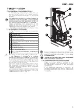
7.4 SAFETY PLATE
Given the appliance’s natural tendency of
becoming unbalanced frontally, it is necessary
to attach the supplied fixing plate (A - Fig. 7.2) to
the back of the installation seat using the M5x12
screws, in order to counterbalance the stresses
when the door is opened.
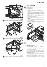
Product images are for illustrative purposes only.
If it is not possible to secure the plate to the back
of the installation seat, it will be necessary to
attach it to one of the two side walls (B - Fig. 7.3).
Product images are for illustrative purposes only.
7.5 FUME EVACUATION SYSTEM
The appliance must be connected to a system
for flue gas evacuation suitable to ensure an
adequate dispersion into the atmosphere of the
combustion products, in compliance with the
standards EN 1856-1-2, EN 1857, EN 1443, EN 13384-
1-3, EN 12391-1, UNI 10683 both in terms of the size
and the materials used in its construction.
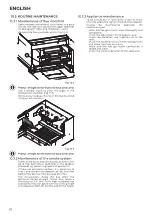
The fume duct (A - Fig. 7.5) between the firebox
and the chimney must have the same cross-
section as the fume outlet of the appliance, as
shown on the technical data sheet “Technical
data”.
The components of the fume evacuation system
must be suitable for the specific operating
conditions and be
marked.
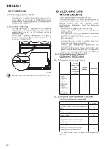
It is appropriate to provide, under the chimney
inlet, a collection chamber with inspection for
solid materials and any condensate (Fig. 7.4).
Do not use glass wool or insulating material with
paper support: they could ignite.
A
Fig. 7.2
B
Fig. 7.3
Product images are for illustrative purposes only.
7.6 FLUE CONNECTION
The flue connection must be tight and the use
of flexible extendible metal pipes is forbidden.
Changes in direction with respect to the
appliance flue gas outlet must be made with
elbow fittings no greater than 45° (preferably
only 30°) with respect to the vertical.
Product images are for illustrative purposes only.
The connection can be made in two ways:
• Direct connection between Ecopalex and
chimney flue. In some cases, it is necessary to
adapt the existing hole in the hood (or make
a new one) in order to facilitate the passage of
the flue gas duct (A - Fig. 7.5)
• Connection using the telescopic pipe.This
solution can be used only if the appliance is
installed in existing fireplaces.
Fig. 7.4
Ø D
H=
2D
max 45°
A
B
C
Fig. 7.5


