31
0523M022-0
6.2 Controllo tensione elettrica
Controllare che la tensione per la quale è predisposto l’impianto
corrisponda a quella di rete. In caso contrario effettuare il cambio
tensione del motore e del trasformatore.
6.3 Allacciamento alla rete elettrica
Accertarsi che la portata minima della rete di alimentazione
corrisponda a quanto indi
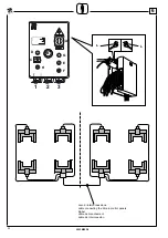
cato sulla targhetta o in figura a lato.
Collegare il cavo di alimentazione (non compresi nella fornitura)
alla morsettiera all’interno della cassetta elettrica principale.
Ruotare l’interruttore principale su 1, se sul quadro elettrico non
si accende la spia bianca ruotare l’interruttore principale su 2.
6.3.1 Cavo per alimentazione elettrica
- L’allestimento del cavo di alimentazione prevede una coppia
presa/spina volante a 3 poli + terra (sezione 10 mm
2
, 400 Volt;
spina da 63A ).
N.B:
eseguire sempre il collegamento nel rispetto delle
norme vigenti nel paese d’installazione.
6
6.3.1 Power cable
- The power cable is equipped with a 3-pole flying plug/socket
ground (10 mm
2
section, 400 Volt; 63A plug).
NOTE:
Connection should always be made in compliance
with the national prevailing regulations.
6.2 Voltage check
Check that the voltage of the system corresponds to the mains vol-
tage. If not, change the voltage of the motor and the transformer.
6.3 Connecting up to the mains
Check that the minimum mains capacity corresponds to the data
on the plate or on the illustration at the side.
Connect the power cables (not supplied on standard) to the ter-
minal board inside the main electrical box.
Turn main switch to 1. Should the white warning light on the control
board turn on, turn main switch to 2.
6.2 Kontrolle der Spannung
Sicherstellen, dass die für die Anlage ausgelegte Spannung
der Netzspannung entspricht. Andernfalls sind die Motor- und
Transformatorspannung zu ändern.
6.3 Netzanschluss
Sicherstellen, dass die Mindestleistung des Speisungsnetzes den
Angaben auf dem Seriennummernschild oder in der Abbildung
entspricht. Speisungskabel (nicht mitgeliefert) am Klemmenbrett
im Hauptschaltschrank anschließen. Den Hauptschalter auf 1
schalten; falls auf der Schalttafel die weiße Kontrolllampe au-
fleuchtet, den Hauptschalter auf 2 schalten.
6.3.1 Speisungskabel
- Das Speisungskabel muss mit einem 3-Pol-Steckdosen-/
Steck Erdung (Schnitt 10 mm 2, 400 Volt; Stecker zu
63A) ausgestattet sein.
Hinweis:
Der Anschluss muss immer unter Beachtung
der geltenden Normen des Landes, in dem das Gerät
aufgestellt wird, erfolgen.
6.3.1 Cable para alimentación eléctrica
- La predisposición del cable de alimentación prevé una pareja
toma/clavija móvil de 3 polos + tierra (sección 10 mm², 400/
Voltios; clavija de 63A).
NOTA:
Proceder siempre con la conexión respetando las
normas vigentes en el país de instalación.
6.2 Control de la tensión eléctrica
Controlar que la tensión para la cual ha sido proyectado el equipo
corresponda con la de red. En caso contrario cambiar la tensión
del motor y del transformador.
6.3 Enlace a la red eléctrica
Comprobar que la capacidad mínima de la red de alimentación
corresponda a los valores indicados en la placa datos o en la
figura al lado. Conectar el cable de alimentación (no incluido en
el suministro) a la caja de bornes dentro del cuadro eléctrico prin-
cipal. Girar el interruptor principal en 1, si en el cuadro eléctrico
se ilumina el testigo blanco girar el interruptor principal en 2.
6.2 Contrôle de la tension électrique
Contrôler que la tension prévue pour l’installation électrique
correspond à celle du réseau.
Dans le cas contraire, effectuer le changement de tension du
moteur et du transformateur.
6.3 Branchement au réseau électrique
Vérifier que la puissance minimum du réseau d’alimentation
correspond aux indications de la plaquette signalétique ou aux
indications de la figure ci-contre.
Brancher le câble d’alimentation (non compris dans la fourniture)
au bornier à l’intérieur de la boîte électrique principale.
Tourner l’interrupteur principal sur 1, si le voyant blanc s’allume
sur le tableau électrique, tourner l’interrupteur principal sur 2.
6.3.1 Câble pour l’alimentation électrique
- L’installation du câble d’alimentation prévoit un couple prise/fiche
volante à 3 pôles + terre (section 10 mm
2
, 400 Volts, fiche de 63A).
N.B.:
toujours effectuer le branchement dans le respect
des normes en vigueur dans le pays d’installation.
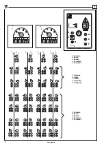
POSTS No.
VOLT
MAINS MIN.CAPACITY
N. COLONNES
VOLTS PUISSANCE MIN. RESEAU
Содержание RAV241XL
Страница 12: ...12 0523M022 0 2 Kg 7000 Vedere pag 14 15 See page 14 15 Q Attenzione warning achtung attention cuidado...
Страница 20: ...20 0523M022 0 7 2 3 4 5 1 4 3 2 1 5 3 5 2 1 4 Kg 20...
Страница 22: ...22 0523M022 0 3 A P F G E D...
Страница 24: ...24 0523M022 0 4 1 2 5 6 NOT AUS 3 NOT AUS 4...
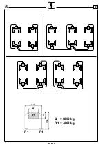
Страница 28: ...28 0523M022 0 6 Q R1 R1 Q 6550 kg R1 4300 kg 1150 600 400 1150...
Страница 34: ...34 0523M022 0 NOT AUS c E D B A 1A 2A 3A F G H 1 2 3 1 2 3 1 1 2 3 P 1 2 3 P P P P 4A 4 4 6...
Страница 38: ...38 0523M022 0 7 NOT AUS c E D B A F G H M L O N NOT AUS...
Страница 42: ...42 0523M022 0 7 NOT AUS c E D B A F G H M L O N 1 2 NOT AUS...
Страница 44: ...44 0523M022 0 7 Attenzione warning achtung attention cuidado Vedere pag 14 15 See page 14 15 Kg 7000 Q...
Страница 46: ...46 0523M022 0 7 B A B A...
Страница 48: ...48 0523M022 0 7 B A NOT AUS c E D B A F G H M L O N NOT AUS...
Страница 50: ...50 0523M022 0 7...
Страница 52: ...52 0523M022 0 7 1 NOT AUS c E D B A F G H M L O N NOT AUS...
Страница 58: ...58 0523M022 0 9 F E...


