background image

u

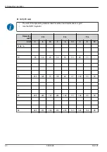
Mount the agitator indicated in the spreading material chart for the respective spreading material.
See 

9.6 Using the fertilizer chart

u

Fill the machine.

u

Place a foil or a hopper for collecting the spreading material under the machine.

u

Set the adjustment lever of the spreading width limiter to the lower stop (lowest spreading width).

u

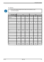
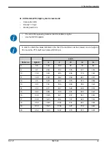
Set the metering slide stop to the scale value from the spreading material chart.

u

Switch on the tractor and the PTO shaft.

u

Open the metering slide for the calibration test time specified before (e.g., 60 seconds). Close the
metering slide when this time has elapsed.

u

Switch off the PTO shaft and the tractor. Remove the ignition key.

u

Determine the collected weight.

u

Compare the actual quantity with the target quantity.

Actual volume = nominal volume: The adjustment lever at the metering slide is set correctly.
End calibration test.

Actual  volume  <  nominal  volume:  Set  the  adjustment  lever  at  the  metering  slide  to  a  higher
scale value and repeat the calibration test.

Actual  volume  >  nominal  volume:  Set  the  adjustment  lever  at  the  metering  slide  to  a  lower
scale value and repeat the calibration test.

8. Calibration

52

5901026

SA 121

Содержание SA 121

Страница 1: ...This operator s and assembly manual is an integral part of the machine Suppliers of new and second hand machines are required to document in writing that the operator s and assembly manual was deliver...

Страница 2: ...ded in your machine Please note that damage caused by incorrect operation or improper use cannot be covered by warranty claims Please enter the type and serial number here together with the year of ma...

Страница 3: ...issioning the machine 13 3 5 5 Hazard zone 13 3 5 6 Running operation 14 3 6 Using spreading material 14 3 7 Hydraulics system 15 3 8 Maintenance and service 15 3 8 1 Qualifications of maintenance per...

Страница 4: ...38 7 4 Installing the machine at the tractor 40 7 4 1 Preconditions 40 7 4 2 Mounting 40 7 5 Mounting the agitator 44 7 6 Setting the spreading vane 45 7 6 1 Increasing the spreading density on the ri...

Страница 5: ...on oil 78 11 6 1 Quantities and types 78 11 6 2 Checking the oil filling level 78 11 6 3 Changing oil 79 11 7 Lubrication 80 11 7 1 Lubricating the drive shaft 80 11 7 2 Lubricating links and bushes 8...

Страница 6: ...Table of contents 6 5901026 SA 121...

Страница 7: ...ns prescribed by the manufacturer Only genuine spare parts from RAUCH may be used as replacements The machine may only be used maintained and repaired by people who are familiar with the characteristi...

Страница 8: ...the new owner The operator s manual is intended for the operator of the machine and anyone involved in operating and maintaining it It must be read understood and applied by every person who is entru...

Страница 9: ...ts with bullet points Property A Property B 2 3 3 References References to other sections in the document are shown with paragraph number header text and or page number Example Please also note 3 Safe...

Страница 10: ...cording to the severeness of the risk and the probability of its occurrence The warning symbols draw attention to the unavoidable residual risks inherent in the design to which users of the machine ar...

Страница 11: ...technical regulations However its usage and maintenance may cause danger to the health and life of the operator or third parties and or the impairment of the machine and other material assets For this...

Страница 12: ...nstructions must also be observed Never let the machine run without supervision Do not ride on the machine while it is working or being transported no passengers Do not use machine parts as steps Alwa...

Страница 13: ...Is all safety equipment at the machine installed and functioning Are all fasteners and load bearing connections tightly installed and in good condition Are the spreading discs the spreading vanes and...

Страница 14: ...ning Only operate the machine with the protective grids in the hopper closed During operation the protective grid must neither be opened nor removed Rotating machine components can cause serious injur...

Страница 15: ...ns Prevent any contamination of the hydraulic circuit Always suspend the couplings in the brackets provided Use the dust caps Clean the connections before coupling them Regularly check the hydraulic c...

Страница 16: ...e Remove the ignition key of the tractor Disconnect the power supply between the tractor and the machine before performing any maintenance and service tasks or before working on the electrical system...

Страница 17: ...ttachment 3 9 2 Road travel with the machine Handling steering and braking performance of the tractor are affected by the attached machine For example an excessive weight of the machine will reduce th...

Страница 18: ...ction stickers front 1 Protective grid in hopper 2 Warning Remove ignition key 3 Warning Danger from hydraulic system in machines with hydraulic drive 4 Instructions Maximum payload 5 Instructions PTO...

Страница 19: ...e that the safety equipment is functioning and not damaged Only operate the machine when the safety equipment is functional Designation Function Protective grid in hopper Prevents body parts from bein...

Страница 20: ...nstruction stickers are components of the machine They must not be removed or modified u Replace missing or illegible warning and instruction stickers immediately If new components are installed durin...

Страница 21: ...documentation Danger due to ejection of material Danger of injury to the whole body caused by ejected spreading material Before commissioning instruct all people to leave the hazard zone spreading ra...

Страница 22: ...d to the machine Fig 5 Nameplate 1 Serial number 2 Manufacturer 3 Machine 4 Type 5 Empty weight 6 Year of construction 7 Model year 3 13 Lighting system front side and rear reflectors u Correctly atta...

Страница 23: ...achine Use the machines in accordance with chapter 1 Intended use The machine consists of the following assemblies Hopper with agitator and outlet Frame and coupling points Drive elements universal dr...

Страница 24: ...verview Rear 1 Hopper 2 Spreading width scale 3 Spreading disc 4 Transmission 5 Spreading width limiters The corresponding agitators are available for the different spreading material You can find the...

Страница 25: ...n Assembly overview front PTO drive Fig 7 Assembly overview Front 1 Frame 2 Coupling points 3 Transmission spigot 4 Universal drive shaft mounting bracket 4 Machine data SA 121 5901026 25...

Страница 26: ...for the basic equipment n Dimensions Data SA 121 Total width 850 mm Overall length 850 mm Filling level 800 mm Distance between center of gravity and lower link point 370 mm Filling width 800 mm Worki...

Страница 27: ...d 200 kg 4 3 2 Technical data for the extensions There are two extensions available for the machine The capacity filling level and total weights may change depending on the selected feature package Da...

Страница 28: ...d to protect the spreading material from humidity The hopper cover is screwed both to the main hopper as well as to the additionally mounted hopper extensions Designation Application TA 4 Basic machin...

Страница 29: ...he mechanical remote control the metering slide and or the spreading width limiter can be operated from the tractor cabin Designation Application Scope of delivery MFB 1 For opening closing the meteri...

Страница 30: ...gitator is suitable for grit and granulated fertilizers Fig 9 RWK 8 agitator n RWK 10 The RWK 10 agitator is suitable for sand salt or a sand salt mixture Fig 10 RWK 10 agitator 4 Machine data 30 5901...

Страница 31: ...ting Attachments are subject to the lighting regulations specified in the traffic regulations Observe the traffic regulations of your country 4 4 8 Lower link point extension This lower link point ext...

Страница 32: ...With smaller working widths and good spreading material quality the agitator speed can be reduced 4 Machine data 32 5901026 SA 121...

Страница 33: ...ion Units Description Obtained by T kg Tractor unladen weight Refer to the tractor operator s manual Measure on scale T1 kg Unladen load on tractor front axle Refer to the tractor operator s manual Me...

Страница 34: ...ool or front rear combination 1 Calculation of the minimum front ballast weight M1 minimum M1 minimum M2 x c d T1 x b 0 2 x T x b a b Write the minimum additional weight in the chart Front tool 2 Calc...

Страница 35: ...capacity Indicate double 2 tires the authorized load value see tire manufacturer indications Table Actual value obtained by calculation Value authorized according to operator s manual Double value of...

Страница 36: ...portation ensures that the machine is transported appropriately Unauthorized persons are to be kept away from the transport route Cordon off the affected areas Transport the machine cautiously and han...

Страница 37: ...s are correctly and tightly positioned In case of doubt please contact your dealer or the factory directly 7 2 Tractor requirements To ensure safe and correct use of the machine of the SA series the t...

Страница 38: ...ance The use of incorrectly dimensioned or inadmissible drive shafts for instance without guard or suspension chain may cause personal injury or lead to damage to the tractor and or the machine u Use...

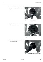
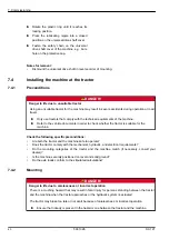
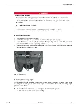
Страница 39: ...iversal drive shaft onto the transmission spigot u Tighten the hex cap screw and nut using a size 17 wrench max 35 Nm Fig 13 Connecting the universal drive shaft u Push the universal drive shaft cover...

Страница 40: ...e tractor is suitable for the machine Check the following specific preconditions Are both the tractor and the machine safe to operate Does the tractor comply with the mechanical hydraulic and electric...

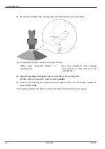
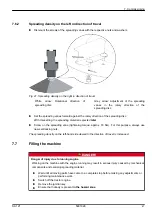
Страница 41: ...ring clips Attach the machine according to the values in the spreading material chart This guarantees correct cross distribution of the spreading material Any oscillating movements during spreading ar...

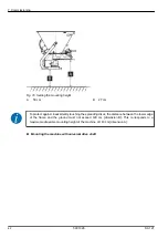
Страница 42: ...e spreading discs the distance between the lower edge of the frame and the ground must not exceed 120 cm dimension B This corresponds to a maximum admissible mounting height of the machine of 143 cm d...

Страница 43: ...me into contact with each other This may cause damage to the universal drive shaft to the gearbox or the machine u Check the clearance between the machine and the tractor u Make sure that there is eno...

Страница 44: ...off and locked to prevent unauthorized starting The agitator is fixed with a bayonet lock The agitators offered can be found under 4 4 Special equipment For dismounting the agitator please refer to 11...

Страница 45: ...spose of the self locking nuts after releasing them and replace them with new ones See 11 5 Spreading vane replacement 7 6 1 Increasing the spreading density on the right in direction of travel u Obse...

Страница 46: ...vanes against the rotary direction of the spreading disc u Reset the spreading vanes against the rotary direction of the spreading disc With this setting the spreading material is ejected earlier u Sc...

Страница 47: ...later u Screw on the spreading vane tightening torque approx 18 Nm For this purpose always use new self locking nuts The spreading density on the left hand side viewed in the direction of travel is in...

Страница 48: ...d road safety of the vehicle machine and tractor Serious personal injury is possible as well as material and environmental damage u Always observe the information in chapter 4 3 Technical data u Prior...

Страница 49: ...machine when it is attached to the tractor Make sure that the tractor is standing on level and solid ground u Secure the tractor against moving Apply the handbrake u Switch off the tractor engine and...

Страница 50: ...l output volume before starting the calibration test The exact forward speed must be known to calculate the nominal output volume To calculate the nominal output volume per minute you will require the...

Страница 51: ...authorized starting An adequately sized hopper is ready for collecting the discharged spreading material The hopper s empty weight is known Using the spreading material chart the pre set values for th...

Страница 52: ...slide for the calibration test time specified before e g 60 seconds Close the metering slide when this time has elapsed u Switch off the PTO shaft and the tractor Remove the ignition key u Determine...

Страница 53: ...stribution variable density grain size and surface and moisture Clumping and damp spreading material Wind drift stop spreading at high wind speeds Blockages or bridge formation e g due to foreign obje...

Страница 54: ...Page 67 NOTICE Possible material and environmental damage The rotating agitator may lead to an increased wear or hardening of the spreading material if the metering slide is closed This hardening can...

Страница 55: ...g slide opening at the numeric scale on the scale plate For this purpose adjust the slide lever to the position determined according to the spreading material chart or by means of a calibration test T...

Страница 56: ...ou want to spread the same amount on both sides u Close the metering slides completely u Determine the position of the stop 2 The correct value can be found in the spreading material chart or determin...

Страница 57: ...rmined position 9 5 Set the spreading width limiter Thanks to the different positions the spreading width limiter makes it possible to adjust the spreading widths from approx 0 8 m 5 m at a mounting h...

Страница 58: ...ansport and many other reasons Together with the machine settings indicated in the spreading material charts this may lead to a different application rate and a less optimal spreading material distrib...

Страница 59: ...l chart for grit 3 5 mm 60 Spreading material chart for sand 0 3 61 Spreading material chart for salt 62 Spreading material chart for fertilizer Link NPK EG PRODUCTS 63 NITROCHALK EG PRODUCTS 64 KORN...

Страница 60: ...tenance is g m Use the RWK 8 agitator Spreading width 2 m 4 m 5 m km h 3 6 10 3 6 10 3 6 10 Scale no 10 65 32 20 32 16 10 26 13 15 250 125 75 125 62 37 100 50 30 20 490 245 147 245 122 73 196 98 59 24...

Страница 61: ...for winter road maintenance is g m Use the RWK 10agitator Spreading width 2 m 4 m km h 3 6 10 3 6 10 Scale no 10 95 47 29 47 24 14 15 465 232 140 232 116 70 20 580 290 174 290 145 87 24 750 375 225 3...

Страница 62: ...l chart for winter road maintenance is g m Use the RWK 10 agitator Spreading width 2 m 4 m km h 3 6 10 3 6 10 Scale no 10 32 16 10 16 8 5 15 43 21 13 21 11 6 20 58 29 18 29 14 9 24 105 52 31 52 26 16...

Страница 63: ...m and the PTO shaft must rotate with 540 rpm Scale no kg min km h 6 8 10 12 14 8 4 6 92 69 55 46 39 9 8 1 162 121 97 81 69 10 11 6 232 174 139 116 99 11 16 9 339 254 203 169 145 12 22 3 445 334 267 22...

Страница 64: ...and the PTO shaft must rotate with 540 rpm Scale no kg min km h 6 8 10 12 14 8 5 2 104 78 62 52 45 9 9 1 182 136 109 91 78 10 13 260 195 156 130 111 11 18 4 368 276 221 184 158 12 23 8 476 357 286 238...

Страница 65: ...cm and the PTO shaft must rotate with 540 rpm Scale no kg min km h 6 8 10 12 14 8 5 8 145 109 87 72 62 9 9 7 242 182 145 121 104 10 13 6 340 255 204 170 146 11 19 3 482 362 289 241 207 12 25 625 469 3...

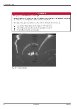
Страница 66: ...damage to the agitator drive u With a closed metering slide even for short periods switch off the machine drive u Open the metering slide until the agitator can discharge the grit or granulated ferti...

Страница 67: ...gitator drive u With a closed metering slide even for short periods switch off the machine drive u Open the metering slide until the agitator can discharge the spreading material in an unhindered mann...

Страница 68: ...tractor motor and the drive of the machine and empty the hopper until no spreading material is discharged u Switch off the machine drive and the tractor engine and lock them to prevent unauthorized s...

Страница 69: ...to the machine and the environment u Any faults occurring must be repaired immediately u Repairs may only be carried out by qualified personnel Troubleshooting requirements Switch off the tractor engi...

Страница 70: ...wear Metering openings clogged By clumped spreading material By damp spreading material By other impurities leaves straw bag residues Blockages Park tractor remove ignition key disconnect the power s...

Страница 71: ...ied by the manufacturer This is assured with original spare parts Before starting any cleaning maintenance or repair work and when troubleshooting switch off the tractor s engine remove the ignition k...

Страница 72: ...X Universal joint of the RWK 10 agitator X X X X Check Wear parts X X Screw connections X X X X RWK 8 agitator X RWK 10 agitator X Spreading vane X X Oil level X X X X Hydraulic hoses X X X 11 2 Wear...

Страница 73: ...during the initial operating hours can loosen screw connections u Check all screw connections for tightness Some components are mounted with self locking nuts u When mounting these components always u...

Страница 74: ...the machine n Cleaning u Clean the outlet ducts and the slide guide area from below only u Only clean oiled machines at washing points fitted with an oil separator u When cleaning with high pressure n...

Страница 75: ...reaches the stop Fig 27 Hopper without protective grid u Lift the agitator out in an upwards direction Fig 28 Dismounting the agitator n Mounting the agitator Mount the agitator in the reverse order...

Страница 76: ...The type and size of the spreader vanes are adapted to the spreading disc Incorrect spreader vanes can cause damage to the machine and the environment u ONLY use spreader vanes which are approved for...

Страница 77: ...the screws of the spreading vane u Attach the new spreading vane to the spreading disc Make sure that you have the correct spreading vane type u Screw on the spreader vane tightening torque 20 Nm For...

Страница 78: ...the oil filling level n Oil level The transmission does not need to be lubricated under normal operating conditions However we recommend changing the oil after 10 years Requirements In order to check...

Страница 79: ...tisfactory when the oil reaches the lower edge of the hole 11 6 3 Changing oil Draining oil u Tilt the machine backwards tilt approx 200 mm u Position the collection vessel under the oil drain plug u...

Страница 80: ...e water drain by setting up sand or earth barriers or by using other appropriate barrier methods Filling in oil Only use SAE 85W 90 transmission oil u Open the filling opening and the checking screw u...

Страница 81: ...he hydraulic hoses for damage on a regular basis or at least before the start of the spreading season by means of a visual inspection u Before the start of the spreading season check the age of the hy...

Страница 82: ...etting up sand or earth barriers or by using other appropriate barrier methods 12 2 Winterizing Thoroughly clean the machine before winterizing refer to chapter 11 3 Cleaning the machine u Open the me...

Страница 83: ...lean and dry Treat the machine with environmentally friendly anti corrosion agents Use protective wax Preservation of hydraulic components such as screw connections hose fittings Preservation of galva...

Страница 84: ...ontains chemical compounds which must be dealt with appropriately u Packaging material is to be disposed of at an authorized waste management company u Observe the national regulations u Packaging mat...

Страница 85: ...th metric thread and standard or fine pitch according to ISO 262 and ISO 965 2 Steel class quality fasteners according to ISO 898 1 Head dimensions of hexagonal bolts according to ISO 4014 to ISO 4018...

Страница 86: ...90 7 63200 12 9 144 106 2 74000 M14 X2 8 8 133 98 59100 10 9 195 143 8 86700 12 9 229 168 9 101500 M16 X2 8 8 206 151 9 80900 10 9 302 222 7 118800 12 9 354 261 139000 M18 X2 5 8 8 295 217 6 102000 1...

Страница 87: ...6 X4 8 8 2482 1830 6 438000 10 9 3535 2607 3 623000 12 9 4136 3050 5 729000 Metric thread with fine pitch Thread Class Tightening torque Max assembly pre load min 0 12 N N m lbf ft M8X1 8 8 26 1 19 2...

Страница 88: ...6X1 5 8 8 218 160 8 87600 10 9 320 236 128700 12 9 374 275 8 150600 M18X1 5 8 8 327 241 2 117000 10 9 465 343 167000 12 9 544 401 196000 M20X1 5 8 8 454 335 148000 10 9 646 476 5 211000 12 9 756 557 6...

Страница 89: ...company representatives of the parent company if you have any questions or doubts Warranty claims must be submitted to the company within 30 days at the latest after the damage has occurred The date...

Страница 90: ......

Отзывы: