


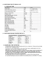


5.2. Tightening the bolts before first use
After you unpack the pump, and before you use it for the first time, check and tighten external
fasteners. Tighten the fluid cover screws first, then the manifold screws. (Refer to Figure 6 for torque
figures). This keeps the manifolds from interfering with tightening the fluid covers.
After using a day check the fasteners again and adjust the torque if necessary. Recommended
frequency for tightening fasteners varies with pump usage, a general guideline is to retighten fasteners
every two months. (Refer to Figure 6 for torque figures).
Exhaust gas may contain dirtying materials. In case of polluting your fluid container, place the exhaust
hose away from it. (Refer to Exhaust Air section. Item 5.7) Fasten the pump foot tightly to the platform
with bolts. Always use seals (teflon, etc) when connecting with bolts.
Pump
Type
Part
Bolt
Torque
N.m
RAN 1.5
’’
M
Air valve
M6
6.8-7.6
Body
M8
15-18
Diaphragm bolt
M12
28-36
Manifold
M8
15-18
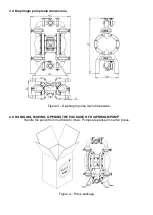
Figure 6
– Pump parts tightening torque table.
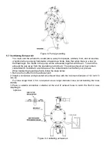
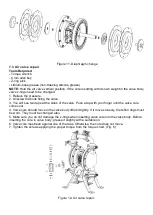
5.3. COMPRESSED AIR CONNECTION
A bleed-type master air valve is required in your system to relieve air trapped between this valve and
the pump. Trapped air can cause the pump to cycle unexpectedly, which could result in serious injury,
including splashing in the eyes or on the skin, injury from moving parts, or contamination from
hazardous fluids. See Fig. 7.
1-Refer to the Figure 7 for the connection scheme. Fix these accessories to the wall or to a
bracket. The air line feeding the accessories must be grounded.
2- Install a filter -
regulator to the air line. Use a 5μ (micron) air filter. The pressure of
liquid outlet should be level with the
air regulator’s. Air line filter is for cleaning the dust
and humidity from the compressor air.
3- Install an air discharge valve below the pump inlet air line. It will be used to discharge
remaining air in the pump. Install the main air valve above all air line accessories and use it
to cut off the main air from the accessories while maintaining or cleaning.
4-Use a flexible air hose between the pump air inlet and accessories at minimum 3/8 inch
(9.5 mm) inner diameter and not longer than 2 meters. For a hose longer than 2 m,
enlarge the inner diameter respectively.
5.4 Important points when connecting compressed air to diaphragm pump
1-
Pay attention not to let any object enter the pump before connecting to compressed air
system.
2-
Before connecting to compressed air system, remove all particles from the system using
blown air.
3-
If the hose connections are sealed with teflon tape, wind the tape a few screw teeth before
the end of the connecting accessory to avoid any teflon pieces entering the system.
4-
When using screw connections, note not to mis-screw or apply excessive power on the
screws.
Содержание E40-SX
Страница 20: ...Figure 13a Pump assembly scheme for RAN 2...


