


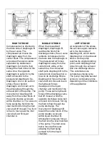


RIGHT STROKE
Compressed air is directed to
the back side of diaphragm B
by the air valve. The
compressed air moves the
diaphragm away from the
center block. The compressed
air pushes the liquid column
separated by elastomeric
diaphragm, forcing the fluid
through the fluid outlet. At the
same time, the opposite
diaphragm is pulled in by the
shaft connected to the
pressurized diaphragm. So,
diaphragm A is on its suction
stroke: the air behind
diaphragm A is forced out to
the atmosphere through the
exhaust port of the pump. The
movement of diaphragm B
away from the center block of
the pump creates a vacuum
within chamber A. The vacuum
force sucks the fluid into the
inlet manifold forcing the inlet
valve ball off its seat. The fluid
is free to move past the inlet
valve ball and fill liquid
chamber A.
MIDDLE STROKE
When the pressurized
diaphragm, diaphragm B,
reaches the limit of its
discharge stroke, the air valve
redirects compressed air to
the back side of diaphragm A.
The pressurized air forces
diaphragm A away from the
center block while, at the
same time, the connected
shaft pulls diaphragm B to the
center block. Diaphragm A is
now on its discharge stroke.
Diaphragm A forces the inlet
valve ball onto its seat due to
the hydraulic forces
developed in the liquid
chamber and manifold of the
pump. These same hydraulic
forces lift the discharge valve
ball off its seat, while the
opposite discharge valve ball
is forced onto its seat, forcing
the fluid to flow through the
pump discharge. The
movement of diaphragm B
toward the center block of the
pump creates a vacuum
within liquid chamber B.
Atmospheric pressure forces
the fluid into the inlet manifold
of the pump. The inlet valve
ball is forced off its seat
allowing the fluid being
pumped to fill the liquid
chamber.
LEFT STROKE
At completion of the stroke,
the air valve again redirects
air to the back side of
diaphragm B, which starts
diaphragm A on its exhaust
stroke. As the pump
reaches its original starting
point, each diaphragm has
gone through one exhaust
and one discharge stroke.
This constitutes one
complete pumping cycle.
The pump may take several
cycles to completely prime
depending on the conditions
of the application
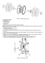
Содержание E40-SX
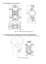
Страница 20: ...Figure 13a Pump assembly scheme for RAN 2...