Ranpump E40-SX Скачать руководство пользователя страница 13


WARNING ! 
Do not run the pump before you make sure all the 
adjustments are OK. 


6.3. Stopping the pump 
 

Cut off the air when the pump is not working. 


WARNING !  

PRESSURIZED EQUIPMENT HAZARD 

The equipment stays pressurized until pressure is manually relieved. 
To reduce the risk of serious injury from pressurized fluid, 
accidental spray from the gun or splashing fluid, follow 

Pressure 

Relief Procedure

 whenever you 


need to relieve pressure 


stop pumping check, clean or service any system equipment


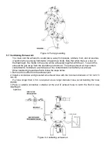
6.4. Pressure relief procedure


1. Shut off the air valve. To relieve the air between the air valve and the pump, use the Air Pressure 

Discharge Valve. 

2. Shut off the Fluid Valve. Place a container under the Fluid Pressure Discharge Valve and open the 

valve. Take the Fluid Discharge Hose off. 

3. To discharge the fluid inside the pump follow the instructions below.  

a. Put on proper safety equipment for the fluid you are pumping. Shut off  the valve on the fluid 

inlet hose if installed. Have a container ready to catch the drainage. Pull out the fluid inlet 
hose from the manifold. Unravel it from the ground if fixed. 

b. Before pulling out the hose from the pump put a container under the pump. Pull it out slowly 

and carefully. 

7.0  ASSEMBLY AND DISMANTLING OF PARTS 


WARNING: 
Before service and maintenance always relieve 
the air and fluid pressure.


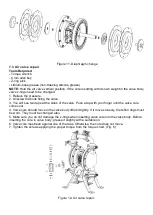
This explanation uses figures defined in part (7.0) line (12) fig. 13.  

 
7.1. Ball check valve repair 
Tools required 

- Torque wrench 
- 5 mm allen key 
- 10 mm wrench 

 
7.1.1 Dismantling 

NOTE: To ensure proper seating, you should change the seats with the ball check valves. 


1. Relieve the pressure in pump. Remove the hoses. 
2. Dismount the pump from the ground. 
3. Remove the upper elbow manifolds and bolts fixing them to the main body using 5 mm allen key 

and 10 mm wrench.  

4. Remove the manifold o-rings, ball cages, valve balls and ball seats from the pump cover. 
5. Turn the pump over. Remove inlet manifolds. Remove the o-rings, ball cages and and valve balls 

from the pump. 


Содержание E40-SX

Страница 1: ...RAGM PUMP 5 0 MOUNTING AND CONNECTING OF DIAPHRAGM PUMP 6 0 INSTRUCTIONS AND MANUAL OF DIAPHRAGM PUMP 7 0 ASSEMBLY AND DISMANTLING OF PARTS 8 0 PERIODIC MAINTENANCE 9 0 STORAGE OF DIAPHRAGM PUMP 10 0...

Страница 2: ...not surpass the strength of minimum system compound j Learn hazards or potential dangers of your fluid k Choose the wet pump parts material resistant to your fluids Refer to the Proper Material Fluid...

Страница 3: ...t or physical damage Use only genuine RAN parts and accessories WARNING Running the pump with hot liquids may cause the surface of the pump to heat up above 80 Co Under these conditions it is pump own...

Страница 4: ...erial Temperature limits BUNA N 12 2 C 65 6 C PTFE teflon 4 C 104 4 C Santoprene 28 9 C 104 4 C Polyurethane 12 2 C 65 6 C V TON 40 C 176 7 C Neoprene 17 8 C 93 3 C EPDM 51 1 C 137 8 C 3 0 DIAPHRAGM P...

Страница 5: ...ces diaphragm A away from the center block while at the same time the connected shaft pulls diaphragm B to the center block Diaphragm A is now on its discharge stroke Diaphragm A forces the inlet valv...

Страница 6: ...MATERIAL DIAPHRAGM MATERIAL A 1 4 A Aluminium 0 Buna N B 1 2 P Polyproplene 1 PTFE teflon BODY MATERIAL C 3 4 C Cast Iron S Santoprene INLET OUTLET D 1 S Stainless Steel E 1 F 2 G 3 3 3 Main parts of...

Страница 7: ...pump main dimensions Figure 3 Diaphragm pump main dimensions 4 0 HANDLING MOVING OPENING THE PACKAGE OF DIAPHRAGM PUMP Handle the pump from manifolds to move Pumps are packed in carton boxes Figure 4...

Страница 8: ...ed in a perpendicular position as shown in Figure 5 Never place the pump at an angle lying on the ground or upside down The pump will not run correctly and check valves and diaphragms will wear out ve...

Страница 9: ...or on the skin injury from moving parts or contamination from hazardous fluids See Fig 7 1 Refer to the Figure 7 for the connection scheme Fix these accessories to the wall or to a bracket The air li...

Страница 10: ...onductive fluid hose or pipe The pump fluid outlet is 2 f 2 Screw the fluid fitting into the pump outlet securely 3 Install a fluid drain valve at the pump outlet 4 Install a fluid shut off valve at t...

Страница 11: ...ent The pump exhaust air may contain contaminants Ventilate to a remote area if the contaminants could affect your process When transferring hazardous fluids follow the steps below 1 Remove the muffle...

Страница 12: ...e of the diaphragm balls and ball seats defines the temperature resistance of the pump 6 1 Flush the pump before use Pump is tested with water Flush the pump with a proper solvent before use if your f...

Страница 13: ...e fluid you are pumping Shut off the valve on the fluid inlet hose if installed Have a container ready to catch the drainage Pull out the fluid inlet hose from the manifold Unravel it from the ground...

Страница 14: ...bly and the diaphragm shaft out of the center housing Hold the shaft with a 17 mm open end wrench and remove the bolt from the shaft 7 Disassemble the remaining diaphragm assembly 8 Inspect the diaphr...

Страница 15: ...at the sides of the valve Push a tap with your finger until the valve core comes out 4 Valve core should move in the valve body little bit tightly If it moves loosely the teflon rings must be worn The...

Страница 16: ...air filter and regulator 2 Check if there is water or moisture in the filter 3 Check the air pressure set value of the pressure regulator 4 After you finish work clean the pump by pumping a suitable s...

Страница 17: ...rings Loose diaphragm shaft bolt Tighten or replace Damaged o ring Replace 5 Fluid in exhaust air Diaphragm is ruptured Replace Loose diaphragm shaft bolt Tighten or replace Damaged o ring Replace 6...

Страница 18: ...weather clean the pump after use 10 0 PRECAUTIONS ON DISPOSING OF THE DIAPHRAGM PUMP Do the precautions before disposing of the pump Discharge the pump completely Disconnect all the hoses Clean the pu...

Страница 19: ...B2711 Pilot shaft cage 5 32 Diaphragm clamp washer 2 10 E2844 Pilot shaft 1 33 E1843 Body 2 11 B2911 Pilot shaft ring 2 34 Body fixing bolt 16 12 E3043 Valve 1 35 Body fixing washer 16 13 E3242 Valve...

Страница 20: ...Figure 13a Pump assembly scheme for RAN 2...

Страница 21: ...ATTACHMENT 1 1 DIAPHRAGM PUMP PERFORMANCE CHARTS Reduce the flow rate by 20 if there are Teflon diaphragms on your pump...

Страница 22: ...ill be made at a reasonable charge which charges may include the costs of parts labor and transportation Gisan s sole obligation and buyer s sole remedy for any breach of warranty shall be as set fort...

Страница 23: ...Gisan Makine San Tic Ltd ti Birlik Sanayi Sitesi 3 Cadde No 83 Beylikd z Istanbul Turkey Tel 00 90 212 875 03 17 pbx Faks 00 90212 875 03 18 E mail Web info ranpump com www ranpump com 25082012...

Отзывы: