


Preparing for Use
R&S
®
NRPxxS(N)
21
User Manual 1177.5079.02 ─ 10
●
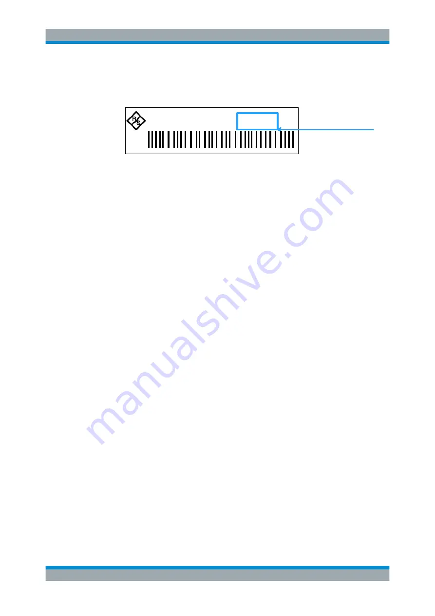
<serial number>
is the individual serial number of the power sensor. The serial
number is printed on the name plate at the rear side of the sensor. It is part of the
device ID printed above the barcode:
ID: 1419.0035K02 - 101441 - Zd
Serial Number
Figure 3-6: Serial number on the name plate
Example:
Serial number of the power sensor: 101441
Default hostname: nrp18sn-101441
Hostname in zero configuration networks, including peer-to-peer networks
The power sensor supports zero configuration networking, used in networks without
DHCP server, such as peer-to-peer networks. Thus, you can connect the power sensor
to a network without setting up services such as dynamic host configuration protocol
(DHCP) and domain name system (DNS), or configuring the network settings man-
ually.
For establishing a connection to the power sensor, try the default hostname as well as
the hostname extended with
.local
as shown in the example below. All communica-
tion for resolving names in the top-level-domain (TLD)
.local
are defined to be exe-
cuted using dedicated local services and ports if no other DNS (domain name server)
is available.
Example:
Default hostname:
nrp18sn-101441
Extended hostname:
nrp18sn-101441.local
3.5.2.4
Assigning the IP Address
Depending on the network capabilities, the TCP/IP address information for the LAN
power sensor can be obtained in different ways:
●
If the network supports dynamic TCP/IP configuration using the Dynamic Host
Configuration Protocol (DHCP), the address information can be assigned automati-
cally.
●
If the network does not support DHCP, the LAN power sensor tries to obtain the IP
address via the Zeroconf (APIA) protocol. If this attempt does not succeed or if the
instrument is set to use alternate TCP/IP configuration, the IP address must be set
manually.
For a description on how to set the IP address manually, refer to the user manual.
Connecting to a Computer