SECTION 7: U-T
UBE
H
EATER
I
NSTALLATION
25
SECTION 7: U-TUBE HEATER INSTALLATION
The fig
u
res in this section pro
v
ide a general o
v
er
v
ie
w
of
component placement in a RADIANT SERVICES™ U-
t
u
be system. The location of some components s
u
ch as
s
u
pports and co
u
plings is cr
u
cial for proper installation.
Assemble the heater components as sho
w
n
on Page 27,
Figure 23
.
For optional reflector config
u
rations for U-t
u
be heaters,
See Page 8, Figure 11
through Page 9, Figure 17
. Install
appropriate s
u
spension hard
w
are, beam clamps, chain or
rod at predetermined locations. Adj
u
stments of chain
length
w
ill pro
v
ide
u
niform pitch.
If any step is
u
nclear, please contact Radiant Ser
v
ices
Ltd. at +44 (0)121.556.4495.
7.1 U-Tube Standard Parts List
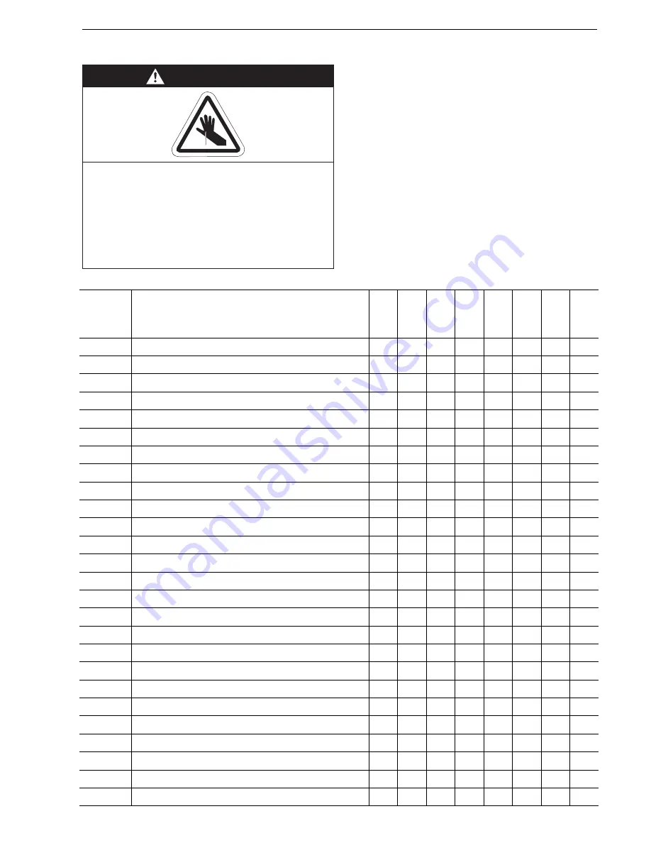
WARNING
Cut/Pinch Hazard
Wear protective gear during installation,
operation and service.
Edges are sharp.
Failure to follow these instructions can result
in injury.
Part No.
Description
BH
15
UT
BH
20
UT
BH
25
UT
BH
25
UT/
EF
BH
30
UT
BH
30
UT/
EF
BH
35
UT
BH
35
UT/
EF
BH
40
UT
BH
40
UT/
EF
BH
45
UT
BH
45
UT/
EF
BH
50
UT
BH
50
UT/
EF
R72XXXXX Burner Assembly (Input and Fuel Varies)
1
1
1
1
1
1
1
1
07260001
Fan Package XP1
1
1
1
1
-
-
-
-
07260002
Fan Package XP2
-
-
-
-
1
1
1
-
07260003
Fan Package XP3
-
-
-
-
-
-
-
1
03051100
Burner Tube, 100 mm x 3048 mm
1
1
1
1
1
1
1
1
91409408
Tube, 100 mm x 3048 mm
-
-
-
2
2
2
2
2
91409423
Tube, 100 mm x 1524 mm
-
2
2
-
-
-
2
2
S5127W
Fan Tube, 100 mm x 3048 mm, with 3048 mm Swirler
-
1
1
1
1
1
1
1
S5134W
Fan Tube, 100 mm x 3048 mm, with 2134 mm Swirler
1
-
-
-
-
-
-
-
01335901
U-Bend
1
1
1
1
1
1
1
1
01329600
Standard Coupling Assembly
2
4
4
4
4
4
6
6
01329700
Coupling Lock
2
4
4
4
4
4
6
6
02750303
Reflector, Aluminium, 2439 mm
4
4
4
6
6
6
8
8
027503SS
Reflector, Stainless Steel, 2439 mm (Optional)*
4
4
4
6
6
6
8
8
02750800
Reflector End Cap, Aluminium
4
4
4
4
4
4
4
4
027508SH
Reflector End Cap, Stainless (Optional)*
4
4
4
4
4
4
4
4
03090100
Tube and Reflector Hanger
4
6
6
6
6
6
8
8
01318901
Tube Clamp Package (including Nut, Washer & Bolt)
1
1
1
1
1
1
1
1
91908004
Wire Form
2
4
4
4
4
4
6
6
03050000
Reflector Support Strap
2
4
4
4
4
4
6
6
03020501
U-Bend Support Bracket
1
1
1
1
1
1
1
1
E0007576
Bow Shackle**
4
6
6
6
6
6
8
8
91107720
U-Clip Package (20 Pieces)
2
2
2
2
2
2
2
2
91912501
U-Bolt M6
2
2
2
2
2
2
2
2
C0090B
Nut M6
6
6
6
6
6
6
6
6
96411500
Lockwasher 6mm
6
6
6
6
6
6
6
6
Содержание BH15UT
Страница 2: ......
Страница 4: ......
Страница 6: ......
Страница 33: ...SECTION 7 U TUBE HEATER INSTALLATION 27 Figure 23 U Tube Assembly Overview mm 200...
Страница 55: ...SECTION 10 OPTIONAL HEATER ACCESSORIES 49 Figure 28 U Tube Angle Mounted Figure 29 Linear...
Страница 71: ...SECTION 16 TROUBLESHOOTING 65 Troubleshooting Flow Chart Linear Double Linear and U Tube...
Страница 73: ...SECTION 16 TROUBLESHOOTING 67 Troubleshooting Flow Chart Multiburner...
Страница 81: ......


