Page 8 of 8
TRIGANO MDC - Haut-Eclair – 72600 MAMERS
9.
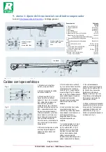
Appendix 1: Adjusting the inertia brake with a compensator
Source:
www.alko-tech.com
- General catalogue.
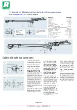
Assembly with
threaded
connectors
Brakes 3062/3081.
Quick set-up Brakes
1636 G / 1637 / 2051 /
2361
Washer
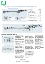
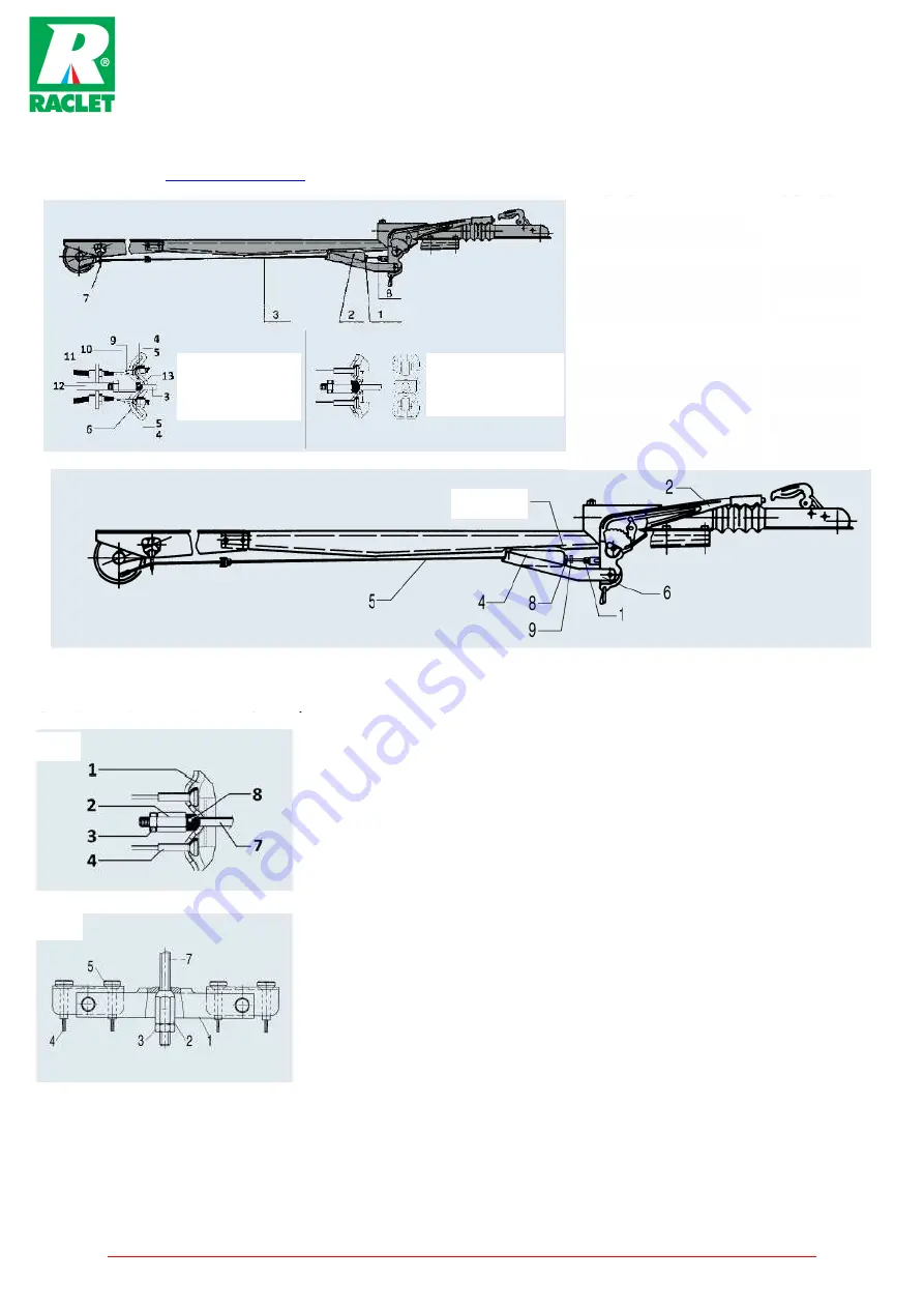
1. Assemble the inertia brake
control and axle on the chassis.
2. Assemble the brake cable
connectors on the crosspiece.
3. Thread the rod rep.5/fig.1
through the central hole in the
crosspiece rep.1/fig.4 or 5, the
return plate rep.6/fig.1 attached to
the handbrake lever and the
compensator rep.4/fig.1. Screw 3 x
M10 nuts + 1 washer onto the rod
connector (one nut positions the
compensator and another is the
lock-nut. The third is the lock-nut
on the thread side of the brake
control). Position the screw nut
and lock nut at least 5mm from the
compensator.
4. Screw the end of the rod into the
thread (lower part) of the brake
control and tighten the lock-nut.
5. The other end of the rod rep.
5/fig.1 is threaded through the
central hole in the crosspiece.
Insert the strut rep. 8/Fig.4 then
screw the long nut rep. 2/Fig.4 or
spherical nut M10 rep. 2/Fig.5 onto
the crosspiece until there is no
more play in the transmission
system. Check the wheels turn
freely when going forwards.
6. Thoroughly manipulate the
brake lever three or four times and
put it into the down position (pull it
towards the front of the coupling
head or ring). Check the sliding
mechanism is fully extended.
7. At the crosspiece rep.1/fig.4 or
5, screw on the long nut rep.
2/Fig.4 or spherical nut M10 rep.
2/Fig.5 by simultaneously turning
the left and right wheels forwards,
until you obtain significant
resistance that feels equal on both
wheels (tightening limit).
Description
Product code
1. Nut MI0 Din 934.8
705 378
2. Compensator
207 502 06 01
3. Rod
See page 85
4. Olive
207 485 05 03
5. Nut M10 Din 934.8
700 109
6.
Single
crosspiece
-
Brake
1637/2051/2361
165 14 19
Single crosspiece - Brake 3062/3081
165 28 43
For tandem axle, dual crosspiece 238 576 assembled)
7. Welded fulcrum for single axle 208
208 193 01 03
Welded fulcrum for tandem axle
208 889 00 03
8. Nut M10 or M12 Din 934.8
705 378 or 705 379
9. Cable
See pages 168-169
10. Long nut - Brake 1637/2051 /2361
706 154
Long nut - Brake 3062/3081
706 281
11. Nut M10 or M12 Din 934.8
705 378 or 705 379
12. Rod holder
228 827
13. Strut - Brake 1637/2051/2361
165 14 90
Strut - Brake 3062/3081
165 42 83
8. Once you have completed this,
unscrew the long nut rep. 2/Fig.4
or spherical nut M10 rep. 2/Fig.5
two or three turns (use a point of
reference). Tighten the nut rep.
3/Fig.4 or 5. Check the wheels turn
freely (a slight rubbing noise is
normal).
9. Press the compensator against
the return plate and screw on the
nut rep. 8/Fig. 1 until you obtain
max. play (J) of 1mm between nut
rep. 8/Fig.1 and the compensator.
Tighten the lock-nut rep. 9/Fig.1.
Cables with spherical connectors
Fig 4
Fig 5

