background image

How to Determine the Currently Graphed and Active Channel  

 
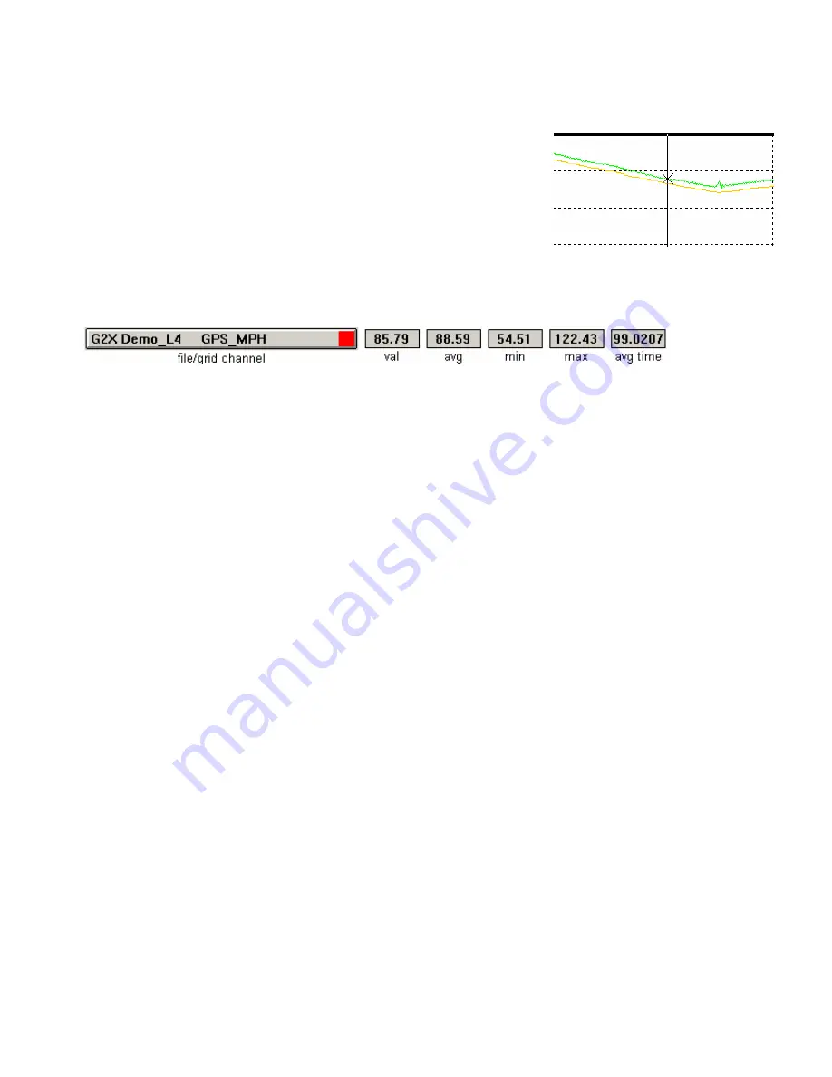
When graphing and reviewing multiple channels, the location of the 
mouse cursor in the Main Graph area is indicated by an 

X

.  The 

X


represents the channel that the mouse cursor will follow, when moving 
left and right in the Main Graph area.  As previously discussed, the 
Channel Buttons display the current values for each channel, according 
to the cursor position in the Main Graph area. 
 
To determine which channel the 

X

 is following, simple look at the Channel Grid Display, found at the 

top, right corner of the Main Graph area.  In addition to noting the current active channel, the Channel 
Grid Display can also provide:  


Val: The current channel value, according to cursor position in the Main Graph Area 
 
Avg: The average value for the active channel. This is determined by averaging the values for the 
channel as displayed in the entire Main Graph area. 
 
Min: The minimum value obtain, over the entire Main Graph area 
 
Max: The maximum value obtained, over the entire Main Graph area 
 
Avg Time: The average time period for the entire Main Graph area or as determined by placing average 
cursors in the Main Graph area. 
 
To move (toggle) the mouse cursor to the next graphed channel: 
 
Place the mouse cursor over the Channel Grid Display. 
 
Left click the mouse button.  This action will update the Main Graph scaling to reflect the next graphed 
channel shown in the Channel Grid Display.  Continue left clicking to toggle through all graphed 
channels.  The TAB key on the keyboard will also perform the same function. 


Averaging Data Using the Averaging Cursor Action 


The DataLink software will automatically calculate average channel data, according to the beginning 
and ending data displayed in the Main Graph area.  There are times however, that a detailed look at data 
in a particular area is desired.  This can be accomplished by placing Averaging Cursors within the Main 
Graph area.   
 
With this action, the DataLink software will provide minimum, maximum and average values for data 
only between the Averaging Cursors. To perform this action: 


70

Содержание G2X

Страница 1: ...rference 10 Movement 10 GPS ANTENNA LOCATION AND MOUNTING PROCEDURES 11 GPS antenna mounting for stock bodied vehicles 11 GPS antenna mounting for open wheel vehicles 11 Connection of the GPS antenna...

Страница 2: ...REPLAY LAP DISPLAY MODE 33 SETUP MODE 33 DATALINK SOFTWARE INSTALLATION INTO THE USER S PC 35 COMPUTER REQUIREMENTS 35 SOFTWARE INSTALLATION 36 COMPACT FLASH CARD READER INSTALLATION 36 GETTING STARTE...

Страница 3: ...ON 70 GRAPHING DATA FROM AN ENTIRE RUN 72 ZOOM COMMAND 72 VIEWING REAL TIME DATA TELEMETRY ON YOUR PC 75 SETTING UP THE G2X REAL TIME TELEMETRY PARAMETERS 75 ENTERING THE DATALINK TELEMETRY FILE PARAM...

Страница 4: ...el Values 101 Understanding Graph Scaling 102 Changing Scaling Per Channel 102 Creating Chart Scaling Sets 103 Predefining Graph Sets for Display 104 Graphing Runfile vs Lapfile Data 105 Zoom Command...

Страница 5: ...sic installation and use of the G2X data logger and DataLink analysis software Thanks again for your purchase We will be looking forward to hearing from you soon Tip Installation and first time usage...

Страница 6: ...le of storing single or multiple runs which are date and time stamped Logging automatically starts when vehicle exceeds 25 MPH Logging stops when vehicle is stationary for greater than 30 seconds Disp...

Страница 7: ...ge 1 G2X Data Logger 2 GPS antenna and cable 3 Display dash and cable 4 12V power RPM cable 5 Cigarette lighter adapter pigtail 6 Three wire pigtail power ground engine rpm 7 Compact Flash memory card...

Страница 8: ...iar with the installation and on track use the G2Xpress Install Guide was created While this guide provides all the basic information required for use review of the remainder of the complete G2X Instr...

Страница 9: ...nal This is typically the type of signal provided by an aftermarket ignition 2 Late model vehicle tach signal Depends upon the vehicle Some have tach outputs that are compatible with the G2X Related i...

Страница 10: ...d Right Side of Dash If no engine RPM is connected vehicle must be moving to change display 1 Short press of left button advances through Lap Disp1 Disp2 2 Short press of right button advances through...

Страница 11: ...ted for 30 seconds 4 Watch the red PWR LED When the logger has written all data to the compact flash card the PWR LED will glow solid 5 Turn G2X power off 6 Pull compact flash card How Data is Stored...

Страница 12: ...If inside and outside lines are desired those laps can be made during a run or at any other time Segmenting a Trackmap Track segmenting is necessary in order to produce all of the segment related rep...

Страница 13: ...on for external power source and tachometer signal RPM 2 optional Provides connection for additional external RPM input DISPLAY Provides connection for the display dash SERIAL Provides connection for...

Страница 14: ...nnect the GPS antenna display and other items Distance from the power and tach source Insure the G2X is located within distance of the power and dash cables Although not required visual access to the...

Страница 15: ...ting for open wheel vehicles By following the above instructions simply insure the antenna is mounted as high as possible on the vehicle Various body panels can possible block satellite signals Insure...

Страница 16: ...s not have this type of tachometer output or you do not wish to display and record the above information you may leave the yellow wire disconnected The pinout of the three wire pigtail is as follows R...

Страница 17: ...determines the action that will be performed according to the current operating mode To assist the user in determining the correct time for each button press the Programming Indicator Red shift light...

Страница 18: ...ios 9 GMT Time Offset 10 Units of Measure 11 Set Default Real time Display Setup mode 1 can be entered either from the Normal or the Lap Replay Display modes To enter Setup Mode 1 1 Press and hold the...

Страница 19: ...actory Default Settings This screen is used to reset the dash to factory configuration To reset select Y as shown below When the screen is exited the dash will be reset to factory defaults 2 Y or n Sh...

Страница 20: ...press Accept selection and go to next setup parameter Long left press Save programming and Exit Setup Engine RPM Source The dash can use the input from the PWR TACH port on the G2X or from the EFI mo...

Страница 21: ...s manner 7000 RPM First two green LED s are displayed 7100 RPM All four green LED s are displayed 7200 RPM All four green and first two yellow LED s are displayed 7300 RPM All four green and all four...

Страница 22: ...ease RPM set point by 50 Long key press Returns at 20000 to 0 3 Auto increase RPM set point by 50 Held Key Every 2 seconds 4 Go to next gear for programming Short left press Short left press Accept se...

Страница 23: ...0 2 Decrement ratio by 5 Medium right key press Return at 0 to 500 3 Increment ratio by 5 Long right press Return at 500 to 0 4 Auto increment by 5 Press and hold right key Return at 0 at 500 5 Go to...

Страница 24: ...programming and Exit Setup Units of Measure Programs the G2X dash to display speed in MPH or KPH After changing this setting you should also reprogram the wheel speed calibration in SETUP Mode 2 if yo...

Страница 25: ...ue entering short presses on the right key until the desired default channel is displayed in the right window Now that both windows are displaying the desired default channels enter Setup Mode1 again...

Страница 26: ...button to send a medium key press two flashes and release 2 The following message will be displayed 3 To confirm you wish to enter Setup Mode 2 press and release the right button to send a short key...

Страница 27: ...ip Auto Calibrate Save Programming and Exit Setup Auto Calibrate RPM 2 Speed If you are using the RPM2 input of the G2X for wheel speed you will need to calibrate this channel before it will read the...

Страница 28: ...unused gears by entering a short key press on the left key Short left press Skip Auto Calibrate Gear Indicator Save Programming and Exit Setup Long left press Skip Auto Calibrate Gear Indicator Save P...

Страница 29: ...until the low power condition is corrected CARD LED 1 The CARD LED will flash YELLOW anytime data is writing to the compact flash memory card 2 If the memory card is removed while data is recording i...

Страница 30: ...rt red flash indicates the end of one search cycle and the start of the next SHORT GREEN The green LED will short flash once for each located GPS satellite LONG GREEN The green LED will long flash onc...

Страница 31: ...ates the search for satellites upon power up Located in the center of the Display Dash is the GPS Satellite Indicator LED Within approximately one minute the G2X should begin to locate and lock on sat...

Страница 32: ...s The dash will then default to Lap Number and Lap Time display mode Lap number and time will be displayed following the completion of the first full lap The location of the Start Finish is at the dis...

Страница 33: ...the G2X with an offset of how many hours your current time is from GMT time The factory default setting is Eastern Standard Time EST The G2X will automatically begin a new recording each time the veh...

Страница 34: ...longer c The G2X must be turned off and back on again to reset the display back to lap 0 3 Setup Mode Allows for setup and programming of the dash and G2X data logger Note If the units in SETUP Mode 1...

Страница 35: ...lights Programming Indicator Length of press for programming buttons Left Right Display Real time display of information Lap Number Decrease Returns toggles lap number to start Lap Number Increase Ret...

Страница 36: ...time data The default displays upon entering Real time mode for the first time after power up is the current lap number on the left display and last lap time on the right display To change the real t...

Страница 37: ...Dash is in Replay Lap Mode the Gear Indicator displays the number of satellites currently in view and locked Setup Mode In addition the Display Dash can also function as a programming device allowing...

Страница 38: ......

Страница 39: ...sh card reader RS 232 serial port or USB serial port adapter CD DVD drive Keyboard and 3 button mouse The DataLink software works best with a screen resolution of 1280 x 1024 or greater The software w...

Страница 40: ...it and double click on Setup to start the installation program 4 Read the instructions on the dialog boxes and answer any questions required We recommend you install the software in the default direct...

Страница 41: ...r The mouse cursor will change to a Position the mouse cursor over toolbar icon for which help is desired and click the left mouse cursor Help on the icon will be displayed 4 To get help on the three...

Страница 42: ...sion on using the DataLink program to view run data files We strongly recommend that you go to G2X Demo File section at this time and work your way through the demo process If you have installed an ea...

Страница 43: ...setup information for your vehicle These changes are made via the G2X_Config or G2X_Config_Metric file To simplify making these changes the default configuration file is opened each time the Datalink...

Страница 44: ...ta is uploaded from your data logger the information contained in the configuration file is copied into the newly created run data file along with the data recorded The run data file then becomes a pe...

Страница 45: ...default communication port used by the DataLink program is the same as the port to which you connected the serial cable This is checked by selecting the Preferences menu item located under the Settin...

Страница 46: ...ton is used to set the options such as record start channel and record threshold used to control the main data logger system or the G2X_Dash channel button is used to set the dash display parameters T...

Страница 47: ...e Configuration The final step is to write the configuration file to your data logger Be sure the serial cable is still connected between the data logger and your PC and the power is connected to the...

Страница 48: ...lengths The diagram on the next page illustrates the correct location of each screw c Carefully remove the top cover There may be some slight resistance due to the status LED connectors d Next to the...

Страница 49: ...e to the status LED connectors d On the G2X printed circuit board directly behind the AUX and EFI ports you will find a two row male connector Plug the module in to this connector Make sure the 3 moun...

Страница 50: ...G2X_Config file are closed at this time Next select the Read VNet Config menu option located in the Edit main menu selection When selected a Message Log dialog box will be displayed and the read confi...

Страница 51: ...odified configuration file to disk You are now ready to begin using your new sensor modules If you wish to change the default configuration on any of the new sensors added to your system simply positi...

Страница 52: ......

Страница 53: ...time data can be reviewed before downloading 2 Ensure that the red PWR LED is solid and not flashing before turning the power off to the G2X It should take 30 seconds after the vehicle speed has gone...

Страница 54: ...at each track An example data path C RacepakData G2X 2005 Infineon If 2005 was entered for the Year and Infineon for Track the above set of folders or directory would be created on the user s C drive...

Страница 55: ...box will be presented If desired enter the current weather conditions If not desired this information can be entered at a later date then select OK The final dialog window to be presented to the user...

Страница 56: ...S_MPH data should now be in view in the Main Graph area 3 Locate and left click the Autoscale icon located in the vertical icon list on the left side of the screen All graphed data from the start of l...

Страница 57: ...f the user The procedures for creating a GPS track map are quick easy and listed in numerical order Step1 through Step 4 At this time our initial run data should still be in view To create a GPS track...

Страница 58: ...of the race course except this is much easier Vehicle Location In order to generate a GPS track map the final step will be to view a lap and create the map from that actual lap Step 4 Create GPS Trac...

Страница 59: ...eft click and drag the mouse curser through the Main Graph area you can follow the location of the vehicle in the GPS driving line data To Set Lap Start place the mouse cursor in the Main Graph area l...

Страница 60: ...erate Segments 1 Insert the desire maximum Lateral G value in the Corner Start input box 2 Insert the desired minimum Lateral G value in the Corner End input box 3 Select the Generate Segments button...

Страница 61: ...timing information which aids in data analysis To manually insert segment markers at desired locations on the track map position the vehicle at the desired location for the entrance segment marker and...

Страница 62: ...loaded in the Configuration file provides a template for data display Incoming data from a new download must first pass through the Configuration file Therefore any track map to be used for testing p...

Страница 63: ...e icon located in the vertical list of icons on the left side of the DataLink screen Insure all changes are also saved in the Runfile also Again while the explanation appears extensive the amount of t...

Страница 64: ...r the Runfile tab and right click To open the fastest lap select the Open Fastest button as shown below The fastest lap will now be displayed as shown in the example below Lapfile Tab All of the data...

Страница 65: ...ion Box In certain applications it is often more useful to compare the data to distance from the start finish line To place the Main Graph area in distance mode select View in the DataLink main menu s...

Страница 66: ...is open and in view Select the Speed Summary Runlog Page tab found at the bottom of the DataLink screen Detailed information concerning segment times entrance and exit speeds along with minimum maxim...

Страница 67: ...g the DataLink software To open another lap for review Place the mouse cursor over the current Runfile tab and right click Select the desired lap Left click the Open Selected button When a new lap is...

Страница 68: ...Remember to change the graph color of a particular channel keep the mouse cursor over the Channel Button and continue to left click until a desired color is obtained 64...

Страница 69: ...open a lap As soon as the lap is open any lap specific data is displayed within the Runlog page For example to activate the data contained within the Segment Compare Runlog page Open a lap The Segment...

Страница 70: ...ive the Reference and Main settings Either selection can be assigned to any open file by using the above instructions The only item that must be remembered is to always select the Reference file first...

Страница 71: ...in an incorrect manner Remember the above data is the same channel from the same lap but with different scaling values Graph Scaling Values Changed per Channel The DataLink program provides two metho...

Страница 72: ...ll use the name New Scaling Enter the name of the channel and the minimum and maximum graph values to be displayed For this example we will rescale the GPS_MPH data channel to graph from 0 to 100 MPH...

Страница 73: ...raph the desired channels in the desired colors At this time we have pre set the channels and colors we wish to save as a Quick Graph To name and save the Quick Graph Select the Quick Graph icon in th...

Страница 74: ...er the entire Main Graph area Max The maximum value obtained over the entire Main Graph area Avg Time The average time period for the entire Main Graph area or as determined by placing average cursors...

Страница 75: ...Channel Grid Display will now be updated to show the current average minimum and maximum values between the two Averaging cursors To view the average values of other graphed channels simply press the...

Страница 76: ...sired channel Left click the Autoscale icon located in DataLink icon list The screen should appear as below As can be seen the entire GPS_MPH from start of logging until end of logging can now be revi...

Страница 77: ...olbar The graph region will zoom in or out accordingly Once you have zoomed in on a section of data you may also want to shift either to the left or right to view additional data without changing the...

Страница 78: ......

Страница 79: ...n An edit dialog box will be displayed In the center of the dialog box will be a Real Time Telemetering Section as shown below Setting up the G2X Real Time Telemetry Parameters This section will conta...

Страница 80: ...ng the Save icon in the toolbar or selecting the Save menu item located in the File main menu selection Entering the DataLink Telemetry File Parameters The final step in setting up the real time telem...

Страница 81: ...A dialog box will then be displayed to allow you to enter the session information the same as when uploading run data Enter the appropriate year track race type and race sequence information as shown...

Страница 82: ...ls will be displayed next to the channel button in the top portion of the display area To display the data from a channel on the graphics screen simply select the channel by left clicking on the chann...

Страница 83: ...or man made obstructions such as walls signs etc Will Rain Affect the GPS Signal We have not encountered an affect from rain in our on track testing and usage Again there could be some type of severe...

Страница 84: ...before attaching to the outgoing email Emailed Runfiles and track maps should be placed in the same directory by the recipient Should multiple users comparing data from the same track use different tr...

Страница 85: ...prevent satellite acquisition My GPS data works at idle but I lose data when I accelerate This is related to electronic interference Check the routing of the GPS antenna cable More than likely the ca...

Страница 86: ...love box etc You can but it makes it really tough to access the compact flash card or to connect the serial cable to the logger if you need to update Serial Cable Related Can I leave the serial cable...

Страница 87: ...nce This makes it impossible to accurately overlay data That is why a creating a trackmap is vitally important following the FIRST run on the track Do not wait until after the day is over and you have...

Страница 88: ...Select the Hardware tab located in the just opened Systems Properties window 5 Select the Device Manager button located in the center right of the Hardware page 6 Locate the Ports COM LPT in the curre...

Страница 89: ...t a closed course map Now if you make additional open course runs you will then be able to select the trackmap upon downloading just the same as if you were making laps on a closed course When compari...

Страница 90: ...abling the channels If you downloaded the G2X_ConfigBoat file from the www g2extreme com website it will be necessary to unzip and place it in the following location on your PC C RacePakData G2X This...

Страница 91: ...is time the G2X_ConfigBoat will now be in view To set as the default config file automatically opens with DatalinkII 1 Select File 2 Select Default Configuration This action will place a check next to...

Страница 92: ...is channel to provide accurate data it is necessary to manually insert the Gear Ratio Prop Pitch and Prop Diameter as found the Prop Data page shown below Prop Slip The Prop Slip channel is created fr...

Страница 93: ...For example if the starting point of the report will be 50 MPH the marker placed in the data can not be located above 50 MPH If the desired starting point for the report will be 50 mph locate the curs...

Страница 94: ...ration data between two markers and provide time data If multiple markers are placed the Datalink II software automatically continues to create time data for each pair of markers as seen in the exampl...

Страница 95: ...ange 1 Close the Datalink program 2 Place the mouse anywhere in the desktop area and right click 3 Select Properties in the dialog window This action will open the Display Properties dialog window 4 S...

Страница 96: ...outing Remember test data can consist of laps acceleration tests lateral g and accel g tests or any variety of information the user desires to obtain Multiple files can be opened in order to overlay...

Страница 97: ...each area can be pre set according to the user s preference That subject will be reviewed at a later time The screen is divided into three sections Channel Buttons A Channel Button is a visual represe...

Страница 98: ...e size Select Preferences then Settings from the Main Menu The following dialog box will be displayed Adjust the Channel Button font and Runlog font through use of the slider bar located below each he...

Страница 99: ...during this test run are now in view in the Channel Button area However no graphed data will appear until the user selects any of the Channel Buttons as discussed in the next section Referring back t...

Страница 100: ...of the values for the remaining data channels are now activated To review the data Place the mouse cursor in the main Graph window and click the left mouse button With the mouse cursor in the main Gr...

Страница 101: ...defined by the track map To view the GPS track map created for this test session Locate and left click the Map Analysis button located in the Run Log Menu page Select the Lap Zoom Runlog tab at the bo...

Страница 102: ...ontinue to left click until a desired color is obtained Remove a Data Channel from the Graph Area Erase To remove all of the graphs currently displayed double left click on the Clear All Graphs icon w...

Страница 103: ...3 simply Select Lap 1 as the Reference by placing the mouse cursorover the Lap 1 tab and clicking the center button on the mouse If you are not using a three button mouse it will be necessary to go to...

Страница 104: ...rovides segment comparison data between two laps Any two laps designated as Reference and Main will be compared Remember all of this data was created strictly through the use of GPS signals As can be...

Страница 105: ...Channel Values The Channel Grid Display will automatically display the min max avg of a channel over the course of one lap To determine the average of a channel between two points other than start fin...

Страница 106: ...nge the scaling within one file The second and preferred method involves the creation of Scaling Sets A Scaling Set has the ability to override all current scaling values and insert a pre defined chan...

Страница 107: ...a will be entered as shown below Select the Insert button to accept the rescaling values The dialog box will appear asshown below Enter the remaining data channels to be rescaled in the same manner Wh...

Страница 108: ...he DataLink toolbar Enter a name for the Quick Graph For this example we used GPSMPH Next click on the Save button to save for later use We have now created and saved a Quick Graph Any time we have a...

Страница 109: ...file as opposed to looking at only one lap of information To graph Runfile data Double click the Clear all Graphs icon in order to remove all graphed data from the Main Graph area and return to distan...

Страница 110: ...a channel scaling is zoomed according to what portion of the graph is included in the zoom box The second method is as follows Place the mouse cursor at the center of the graph region to be zoomed Lef...

Страница 111: ...By doing so this reduces the technical expertise required for data analysis The G2X_Demo Runfile included with this demo includes a set of standard Runlog pages The following section provides detailed...

Страница 112: ...user s computer weather data will automatically download into the appropriate areas of this page Create GPS Track Map The Create GPS Map page is utilized to create a GPS based track map Following the...

Страница 113: ...p with zoom features The zoom feature allows the user to zoom into any area of the track map for detailed data analysis Map Report The Map Report page provides detailed speed analysis for each track s...

Страница 114: ...egment timing information Segment Report provides a review of all segment times for all laps contained within one Runfile Speed Report provides an analysis of segment speed for two laps Segment Compar...

Страница 115: ...area In the below example the Question Goes Here was inserted in the first area with an answer of Answer Goes Here in the second section To set up the pages simply insert the desired text in the firs...

Страница 116: ...Calculator Page The Tire Temperature PSI page provides the user a means of logging tire temperatures following each run Upon insertion of all tire temperature data the page will calculate average per...

Страница 117: ...pdate will be accompanied by a cover sheet detailing the updated information All updates will be available online at www g2extreme com or may be obtained by contacting the Racepak office If desired th...

Страница 118: ...ons of chassis scales By inputting the four corner weights of a scaled vehicle the Chassis Scaling page can calculate the following information 1 Total Weight 2 Cross Weight 3 Cross Weight Percentage...

Страница 119: ...ls 2 Open at least two Lapfiles 3 Select a Reference and Main lap file as outlined in the G2X Instruction Manual 4 For this example graph the MPH_Difference Delta channel for both the Reference and Ma...

Страница 120: ...lap time and lap number 4 Select the Runlog Menu tab found at the bottom of the DatalinkII software 5 Locate the Write Start Finish Position to Card button as found under the Favorite Log Page Shortcu...

Страница 121: ...and hot tire pressure data is inserted the system can provide the following information 1 Left Front Pressure Gain 2 Right Front Pressure Gain 3 Left Rear Pressure Gain 4 Right Rear Pressure Gain Tra...

Страница 122: ...eading as shown below The user is presented with two options 1 Export Standard TrackVision Data 2 Export Customer TrackVision Data Exporting Standard TrackVision Data 1 Select the Export Standard Trac...

Страница 123: ...rsor at the beginning of the channel name left click to select and use your computers Erase button to clear the channel name 3 To add a channel place the mouse cursor below the last channel in the lis...

Страница 124: ...ction Manual Updates Version 2 8a 1 Added G2X_Config_Metric configuration file for metric units See section The G2X_Config Configuration File for instructions Date 1 31 2007 Application DatalinkII Ver...

Отзывы: