90
Serial and TCP Protocols
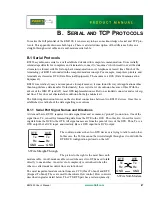
cable connector. Using a 10-conductor, 50 mil pitch ribbon cable, you can crimp a 10-pin IDC (2x5) socket
on one end of this cable. To the other end, you can crimp a DE9 M if you remove the 10th conductor at the
crimping position. Now, you now have a normal DTE connector.
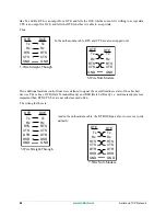
Using SER3 as a 5- or 9-wire port, precludes the use of SER4. If you use SER3 and SER4 as two 3-wire
ports, you will have to customize a cable to connect the appropriate pins to two separate serial devices.
The 5th serial port is special purpose, and not described here. It is the RS-485 port. Please see
for more information on this port.
B.1.2 Electrical Signals
Having established the signal names, we now describe the electrical signals used on those lines.
All of the RS232 lines use a n/-12V signal level. This may be as low as +/-5 V and be valid, as is
done with the EM1500 drivers. The receiver will usually switch at about +2 V to allow for attenuation over
long lines. Because the switching threshold is above zero volts, some equipment does not supply the stan-
dard negative voltage, instead using 0 V. This is not recommended, but will usually work.
The Tx and Rx lines use -12 V to indicate a “1,” and +12 V to indicate “0.” This is inverted from what you
would expect intuitively, however, the inversion is handy because it is actually the “1” state that represents
an idle line. Thus, if equipment is not connected or powered off, the receiver will see zero volts which the
driver will interpret as a “1.” If this were not so, the receiver would see all sorts of garbage when the
sender was powered off.
All the other lines use +12 V to indicate “active” or “asserted” state, and -12 V when inactive. A discon-
nected input will yield 0 V, which will be interpreted as “inactive,” which is as it should be.
Now the computer equipment which is using RS232 is probably happier with TTL drive levels, which are
0 and 5 V, and nothing happily accepted outside this range. Because of the voltage differences, the RS232
signals need to be processed by a level converter. The level converters are always inverting, in that they
turn -12 V on the RS232 side into +5 V on the TTL side; and +12 V is converted to 0 V. The same level
conversion, and inversion, is applied in both directions.
Because of the prevalence of TTL levels, there is a new level of confusion when talking about RS232. Are
we talking about true RS232 levels, or the same signals converted to TTL? Unless otherwise stated, RS232
refers to the true signal levels of +/-12 V. Only if “TTL levels” are explicitly mentioned, should the 0/5 V
levels be assumed.
The reason this subject is brought up here is that, on the EM1500, SER3 can be configured for either set of
voltage levels.
B.1.3 Data Signaling Conventions
Now that the electrical signal levels are defined, it is useful to know how those signals change with time,
and what meaning is associated with them. Most of the action occurs on the Tx and Rx lines. The other
lines usually change at a relatively slow rate.
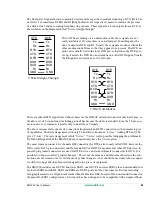
The Tx and Rx lines work the same way, only in opposite directions. Each byte of data is transmitted as a
sequence of transitions of the line. Each bit of the byte takes a fixed interval of time, known as the bit rate.
The line is initially idle at the “1” state. To start transmitting a character, the line is brought to “0” for one
bit time. This is known as the start bit. Then, the bits in the data byte are shifted out (LSB first) with each
bit driving the line state for its allotted bit time. Finally, the line is brought back to the “1” state for a single
Содержание EM1500
Страница 14: ...10 www rabbit com Introduction...
Страница 22: ...18 www rabbit com Getting Started...
Страница 76: ...72 www rabbit com EM1500 Configuration...
Страница 90: ...86 www rabbit com EM1500 Specifications...
Страница 104: ...100 www rabbit com Serial and TCP Protocols...
Страница 118: ...114 www rabbit com EM1500 FAQ...


