EM1500 User’s Manual
17
2.3.4 Digital Input and Relay
To test the relay and the digital input, follow these steps:
1. Move the jumper at H2 on the Demo Board to position 3-5 and 4-6.
2. Using the 9-wire assembly, wire IN0 to Relay NC.
3. Using the 9-wire assembly, wire IN1 to Relay NO.
4. Connect Relay Common from the 9-wire assembly to SW1 on the Demo Board.
5. Toggle the relay button in the AUX tray. When the relay is on the button is orange, when off, the
color changes to gray.
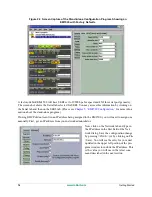
Press down SW1 on the Demo Board. Depending on the state of the relay you will see either IN0 or IN1
change from bright green to dark green in the AUX tray.
•
When the relay is open, contact is made with the normally closed pole; therefore, pressing SW1(i.e.,
completing the circuit) causes the state of IN0 to change, which is then reflected in the button color
for IN0.
•
When the relay is closed, contact is made with the normally open pole; therefore, pressing SW1(i.e.,
completing the circuit) causes the state of IN1 to change, which is then reflected in the button color
for IN1.
Содержание EM1500
Страница 14: ...10 www rabbit com Introduction...
Страница 22: ...18 www rabbit com Getting Started...
Страница 76: ...72 www rabbit com EM1500 Configuration...
Страница 90: ...86 www rabbit com EM1500 Specifications...
Страница 104: ...100 www rabbit com Serial and TCP Protocols...
Страница 118: ...114 www rabbit com EM1500 FAQ...

