EM1500 User’s Manual
89
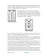
The final pair of signals that are commonly used are rather specific to modem technology. DCD (Data Car-
rier Detect, or sometimes RLSD) and RI (Ring Indicator) are respectively meant to indicate the presence
of a data 'carrier' and an incoming telephone ring cadence. These signals are both outputs from a DCE as
shown below in the diagram labeled “9-wire straight-through.”
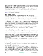
If two DTEs are talking via a null-modem cable, these signals are not
really available at all, since there is no natural pair. Something must be
done to simulate DCD and RI. Usually, these signals are derived from the
other modem control lines so that they appear to be present. The DCD on
each end is usually tied to the local DTR pin, so that when the DTE pow-
ers up, it asserts the DTR line, and reads back a valid DCD signal. Usually
the RI signal is not relevant, so it is left open.
There are other RS232 signal lines defined, however the IBM AT serial port connector only had 9 pins, so
the above set of 9 connections (including ground) has become the de facto standard. Even the 25-pin con-
nectors, also very common, typically only connect these 9 signals.
The above incremental sequence of connections implements an RS232 connection with an increasing set
of capabilities. The first arrangement, with only Tx and Rx, is known as “3-wire.” Adding RTS and CTS
gives “5-wire.” The last arrangement is full “9-wire.” “7-wire” is also possible (dropping the problematic
DCD and RI signals) but the EM1500 does not specifically have the 7-wire option.
The most common connector is the male DE9 connector (for DTEs, also loosely called DB9, however the
DB is really for 25-pin connectors) and the female DE9 or DB25 for modems and other DCE devices. In
general, plug (male) connectors are used for DTE devices, and socket (female) connectors for DCE. It is
possible to obtain so-called “gender changers.” This is not the same as a null-modem cable since the con-
nections are not crossed over. Avoid the use of gender changers—they should be used only when a connec-
tor of the wrong gender has been (mis)designed into a piece of equipment.
The EM1500 includes one DE9 M, known as SER1, one DE9 F, known as SER2, plus a non-standard con-
nector for SER3 and SER4. SER3 and SER4 are RS232 ports, but they has some restrictions including
being implemented on a 10-pin header rather than the familiar DE9. In spite of the non-standard connector,
the pinout for SER3 configured as a 9-wire port has been designed to be compatible with a simple ribbon-
DTE
Tx
Tx
Rx
Rx
GND
GND
DCE
RTS
RTS
CTS
CTS
DTR
DTR
DSR
DSR
DCD
DCD
RI
RI
9-Wire Straight-Through
DTE
Tx
Tx
Rx
Rx
GND
GND
DTE
RTS
RTS
CTS
CTS
DTR
DTR
DSR
DSR
RI
RI
DCD
DCD
9-Wire Null-Modem
Содержание EM1500
Страница 14: ...10 www rabbit com Introduction...
Страница 22: ...18 www rabbit com Getting Started...
Страница 76: ...72 www rabbit com EM1500 Configuration...
Страница 90: ...86 www rabbit com EM1500 Specifications...
Страница 104: ...100 www rabbit com Serial and TCP Protocols...
Страница 118: ...114 www rabbit com EM1500 FAQ...

