background image

Biasi SG Pro Series 

Page 23 


The electricity to the boiler shall come from a dedicated breaker in the electric  

service box. A service switch should be mounted on the side of the boiler so the burner 
technician can service the burner and controls. The electrical wiring should be routed so as not 
to interfere with normal servicing of the boiler. Wiring done in the field between devices not 
attached to boiler shall conform with the temperature limitations for type T wire (63F/35C) or 
other specified wire as applicable when installed in accordance to manufacturer's  
instructions and wiring diagrams. 


If an external electrical source is utilized, the boiler, when installed, must be electrically 

bonded to ground in accordance with the requirements of the authority having jurisdiction or, in 
the absence of such requirements, with the National Electrical Code, ANSI/NFPA 70 and/or the 
Canadian Electrical Code Part 1, CSA C22.1, Electrical Code. 


Wiring the boiler 


Power for the SG Pro series boiler 

should be brought to the junction box in the 
back of the boiler under the top panel 
(Figure 12.1).  Line voltage from the fire-o-
matic should be applied to the black wire.  
The neutral leg should be connected to the 
white wire and the ground to the green 
wire.  If a external circulator will be 
controlled by the Hydrolevel control, use 
the red wire in the junction box to power the 
circulator.  The dry contact switch for the 
Hydrolevel low voltage control circuit (TT) 
should be connected to the terminals on the 
right rear of the boiler (Figure 12.2).   


Direct Vent Applications 
 

On applications with Direct Vent Burners a 

field installed jumper 

is required from terminal #3 to 

terminal #7. The capped off black wire also needs to be terminated to #7. This provides a fused 
constant 120volt power supply for the post purge of the burner.  


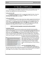
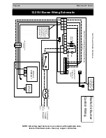
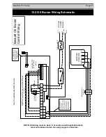
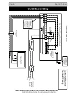
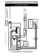
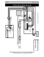
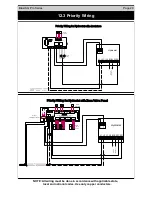
Refer to pages 26 to 28 for oil wiring diagrams and page 29 for gas  

wiring diagrams. 

12.1  Wiring


Figure 12.1 

Figure 12.2 

Содержание SG-3

Страница 1: ...erformed by a qualified installer service agency or the gas supplier Please Read Instructions Carefully Save for Future Reference Distributed By QUINCY HYDRONIC TECHNOLOGY INC 3560 LAFAYETTE RD PORTSM...

Страница 2: ...Page 2 Biasi SG Pro Series...

Страница 3: ...The installing contractor is the best judge of a system s specific requirements as well as the local availability of certain makes and models of controls and accessories The preceding does not apply...

Страница 4: ...losion Diagram 2 8 Boiler Location 3 9 Installation of Boiler Trim Kit Components 4 10 12 Piping the Boiler 5 13 Intake Venting 6 14 15 Exhaust Venting 7 16 Common Exhaust Venting 7 1 16 17 Block Flue...

Страница 5: ...t all times Keep the boiler area clean and free of all fire hazards Please read the literature and warranties supplied by the manufacturers of the various accessory equipment This equipment is warrant...

Страница 6: ...ed with those of influenza and the highest incidence of poisoning occurs at the onset of cold weather or during flu season A victim may not experience any symptoms only one symptom or a few symptoms S...

Страница 7: ...ponents USE ONLY THE LISTED BOILER SYSTEM COMPONENTS AND SPECIFIED OIL AND GAS BURNER COMPONENTS SUPPLIED WITH THE BIASI SG BOILER 1 General Information Boiler Model Heating Capacity Gross Input Burne...

Страница 8: ...hammer cushioned with a block of wood Apply boiler mastic to one section only and slide sections together Install the four draw rods and draw the sections together evenly measure with ruler or tape me...

Страница 9: ...sides and rear of the boiler 2 18 from the flue pipe in any direction 3 24 inches from the front of the boiler DANGER The boiler must be located on a non combustible floor A smooth level concrete floo...

Страница 10: ...amper w Manual Reset Spill Switch Gas Burner Only BIASI SG T handle Gas Cock Alternative Location Drip Leg Gas Train Positive Pressure Gas Fired 4 1 Boiler Trim Components Union Trim Kit Components 1...

Страница 11: ...Tapping 11 2 Boiler Return Tapping 3 4 Boiler Drain Tapping 3 4 Hi Limit Control or PRV Tapping 3 4 PRV or Hi Limit Control Tapping 6 Exhaust Breeching 2x 26 3 4 Control Panel Pressure Sensor Tapping...

Страница 12: ...ach with a washer and a nut 4 Next place the door catch under the top post of the side opposite that on which the hinges are mounted This is mounted in a similar manner to the hinges Tighten with a wa...

Страница 13: ...t off be installed Install manual and or automatic air venting devices at the high points in the system to eliminate trapped air The weight of all piping should be supported by suitable hangars and fl...

Страница 14: ...hall not be located closer than 3 inches from either the top or bottom of the enclosure and shall connect directly or by ducts with the outdoors The area of each opening shall be equal to one square i...

Страница 15: ...ll ceiling joints between wall panels at penetrations for plumbing electrical and gas lines and in other openings If the building is of tight construction air openings must be provided from the outsid...

Страница 16: ...timing control to prevent problems with fogging and nozzle post drip The determining connection from the boiler to the chimney should be as short as possible with a minimum number of elbows The equiv...

Страница 17: ...aust fans fireplace dampers and any other gas burning appliance to their previous condition of use 7 Any improper operation of the common venting system should be corrected so the installation conform...

Страница 18: ...A good target is 11 to 12 75 of CO2 or 6 0 to 3 5 of O2 7 Checking for a zero smoke level in the flue pipe To ensure proper burner setup gauges should be used to check things such as the pump pressure...

Страница 19: ...er Model EZ 1 EZ 1 EZ 1 Firing Rate 0 91 1 22 1 52 Insertion Depth 3 5 3 5 3 5 Nozzle 65 x60 1 00 x 60 1 25 X 60 Spray Pattern B B B Pump Pressure 175 psi 135 psi 140 psi Head 60 65 85 1 00 1 10 1 25...

Страница 20: ...12 for the proper setup of the burner To determine how much gas is coming into the burner or to set the gas meter correctly the following formula can be used The chart to the right can be used to dete...

Страница 21: ...gas valve When installing the boiler make sure a pipe compound resistant to the action of liquefied petroleum is used Check piping for leaks Always check leaks with a water and soap solution DO NOT U...

Страница 22: ...ture conserves fuel by reducing boiler temperature whenever possible without sacrificing comfort The Economy Feature is factory set for a 1 zone heating system To adjust touch the SET UP button The sc...

Страница 23: ...70 and or the Canadian Electrical Code Part 1 CSA C22 1 Electrical Code Wiring the boiler Power for the SG Pro series boiler should be brought to the junction box in the back of the boiler under the t...

Страница 24: ...EXTERNAL CONTROL HYDROSTAT 3250 Touch Control T T SG Pro Touch Screen Control Panel Internal Wiring B R G W B R G W L1 L2 C1 C2 B1 B2 ZC ZR GND 5 L N 3 4 10 9 8 7 6 11 12 RIELLO PRIMARY N L X CHASSIS...

Страница 25: ...TERNAL CONTROL HYDROSTAT 3250 Touch Control T T SG Pro Touch Screen Control Panel Internal Wiring B R G W B R G W L1 L2 C1 C2 B1 B2 ZC ZR GND 5 L N 3 4 10 9 8 7 6 11 12 SG Pro with Beckett NX Burner F...

Страница 26: ...2 C1 C2 B1 B2 ZC ZR GND 5 L N 3 4 10 9 8 7 6 11 12 SG Pro with Carlin Burner Fuse GND GND C2 C1 B1 B2 limit line neutral grnd Carlin 70200 Please note the Black and Red wires are connected to B1 Cauti...

Страница 27: ...L CONTROL HYDROSTAT 3250 Touch Control T T SG Pro Touch Screen Control Panel Internal Wiring B R G W B R G W L1 L2 C1 C2 B1 B2 ZC ZR GND 5 L N 3 4 10 9 8 7 6 11 12 SG Pro with Carlin EZ GAs Burner Fus...

Страница 28: ...ND SWITCH ON EXTERNAL CONTROL HYDROSTAT 3250 Touch Control T T SG Pro Touch Screen Control Panel Internal Wiring B R G W B R G W L1 L2 C1 C2 B1 B2 ZC ZR GND 5 L N 3 4 10 9 8 7 6 11 12 SG Pro with Gas...

Страница 29: ...ZONE2 T A DHW Aquastat DHW Pump FOUR ZONE ZONE VALVE CONTROL WITH OPTIONAL PRIORITY OFF ON ZONE 4 PRIORITY MOD E RESE T ZVC 404 1 2 3 4 ZONE 1 1 2 3 4 ZONE 2 1 2 3 4 ZONE 3 1 2 3 4 ZONE 4 ZONE 4 RELAY...

Страница 30: ...the Pressure Relief Valve and manually set it off three times to ensure it is operating normally and not leaking 3 If a Low Water Cut Off is installed follow the manufactures suggested maintenance an...

Страница 31: ...____________________ ______________________ _________________________ ______________________ Burner Manufacturer Type of Oil Burner Burner Model No Burner Serial No Nozzle Manufacturer Nozzle Spray An...

Страница 32: ...ext step 7 Return the manual valve on the combination gas valve to the on position by reversing step 5 8 Turn on all electric power to the appliance 9 Set thermostat to the desired setting 10 If the b...

Страница 33: ...Biasi SG Pro Series Page 33 Notes...

Страница 34: ...Page 34 Biasi SG Pro Series Notes...

Страница 35: ...Biasi SG Pro Series Page 35 Notes...

Страница 36: ...installation conforms to all codes and ordinances 4 This warranty does not apply to boilers which are subject to misuse abuse neglect alteration accident excessive temperature excessive pressure or co...

Отзывы: