Fröling Heizkessel- und Behälterbau Ges.m.b.H, Industriestrasse 12, A-4710 Grieskirchen
Tel. +43 (0) 7248 606-0 Fax +43 (0) 7248 606-600 [email protected] www.froeling.com
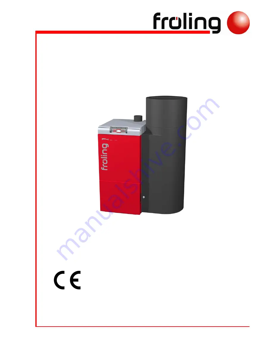
Assembly instructions
P4 Pellet 8 - 60
Read and follow the assembly instructions and safety information
Subject to technical change.
Summary of Contents for P4 Pellet 15
Page 2: ......