Riello 20116107, Installation And Maintenance Manual
The Riello 20116107 Installation and Maintenance Manual is a comprehensive guide to help users efficiently set up and care for their product. Available for free download at our website, this essential manual ensures users have all the necessary information to install and maintain their Riello 20116107 effectively.
Share
Download


Reviews:
No comments
Related manuals for 20116107

8800 Series
Brand: RBI Pages: 44

i 24
Brand: IDEAL Pages: 8

C750
Brand: Harsco Industrial Pages: 58

Aerco BMK 5000
Brand: Watts Pages: 167

INSIEME EVO 25
Brand: Riello Pages: 44
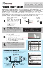
ALTA-120
Brand: U.S. Boiler Company Pages: 2

Alpha CD18S
Brand: Alpha Pages: 36

CGS2 Series
Brand: Alarko Pages: 68

Ultimate 50CF
Brand: Glo-warm Pages: 20

POWER MAX 100
Brand: Beretta Pages: 60

ECOMFORT 30 HE
Brand: Sime Pages: 40

WBV SERIES
Brand: PEERLESS Pages: 17

SERIES TC
Brand: PEERLESS Pages: 30

PSC II Series
Brand: PEERLESS Pages: 40

EP 2140
Brand: LAVAZZA Pages: 43

Celtic FF
Brand: Chaffoteaux & Maury Pages: 44

EBE Express Series
Brand: Ecoboil Pages: 4

EB Rapid Series
Brand: Ecoboil Pages: 4


