


501510 Rev. S
Field
–
Replaceable Units (FRUs)
7-61
4.
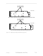
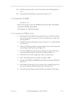
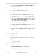
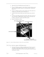
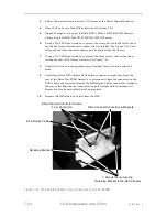
Reconnect the ribbon cable to the INTER connector on the left side of the PCBA
as seen from the front of the RLS. See Figure 7-36.
5.
Reconnect the ribbon cable to the SENSOR connector on the right side of the
PCBA as seen from the front of the RLS. See Figure 7-36.
6.
Install two cable ties to hold the power cable that runs between the Drive Bay
and Executive PCBAs.
7.
Reinstall the rightmost Tape Drive Assembly as described in Section 7.11.2.
8.
Reinstall the Carriage Assembly into the RLS as described in Section 7.7.2.
9.
Proceed to Section 7.24 to calibrate the RLS.
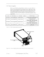
7.18
Drive Interface Adapter (DIA)
Passive Adapter P/N 501677-01-7
Quick-swappable Tape Drive Assemblies
Active Adapter P/N 501687-01-6
Hot-swappable Tape Drive Assemblies
SAS Adapter
P/N 502087-01-8
The RLS Power Supply Module(s) must be removed before a DIA can be replaced. The
DIA type (Quick / Hot swappable) installed can be changed at this time. No calibra-
tion is required after replacing/changing a DIA.
Tools Required: No. 2 Phillips Screwdriver
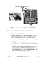
CAUTION
The pins of the four Channel(1-4) connectors on both sides of the Drive Bay
PCBA Assembly are easily bent while working around the PCBA. If a bent pin
is not straightened perfectly before a Tape Drive or DIA PCBA is installed, it is
quite likely that the pin will get permanently damaged during the insertion of
the mating connector.
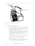
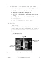
7.18.1
Drive Interface Adapter Removal
1.
Remove power from the RLS by first pressing the power switch off and then re-
moving the power cord (two power cords if dual-redundant power supply mod-
ules are installed).
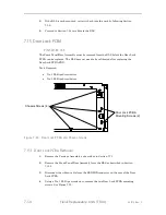
2.
Disconnect all SCSI cables from the Tape Drives (T1-T4). Note how they were
connected so they can be reconnected in the same manner.
3.
Follow the instructions in Section 7.21 to remove the Power Supply Module(s).
Содержание RLS-4470
Страница 1: ...RLS 8000 Tape Library Technical Service Manual 501510 Rev S...
Страница 2: ......
Страница 14: ...xiv 501510 Rev S This page left blank intentionally...
Страница 16: ...1 2 Introduction 501510 Rev S Table 1 1 Applicable Documents...
Страница 20: ...1 6 Introduction 501510 Rev S This page left blank intentionally...
Страница 23: ...501510 Rev S Description and Theory of Operation 2 3...
Страница 34: ......
Страница 50: ...3 16 The Operator Interface 501510 Rev S This page left blank intentionally...
Страница 64: ...4 14 The Maintenance Menu 501510 Rev S This page left blank intentionally...
Страница 65: ...501510 Rev S The Private Menu 5 1 5 The Private Menu...
Страница 69: ...501510 Rev S The Private Menu 5 5 10 Close the Front Panel Door...
Страница 144: ...7 40 Field Replaceable Units FRUs 501510 Rev S 4 Reinstall the Carriage Assembly into the RLS as described in Section 7...
Страница 184: ...8 6 Firmware Updating 501510 Rev S Figure 8 2 Sample of the Library Firmware Upload Progress Screen...
Страница 188: ...8 10 Firmware Updating 501510 Rev S Figure 8 7 Properties Screen...
Страница 205: ...501510 Rev S RLS Expansions 9 13 This page left blank intentionally...


