Qlogic QLogic 12000 Series Скачать руководство пользователя страница 1

D000140-001  B

QLogic 12000 Hardware Installation Guide

Содержание QLogic 12000 Series

Страница 1: ...D000140 001 B QLogic 12000 Hardware Installation Guide...

Страница 2: ...at any time without notice Applications described in this document for any of these products are for illustrative purposes only QLogic Corporation makes no representation nor warranty that such appli...

Страница 3: ...5 Tools and Equipment Required 1 5 Check the Installation Site 1 5 Mark the Rack 1 6 12200 12300 Installation 1 7 Four Post Standard Depth Rack Installation 1 7 Mounting Hardware Kit Contents 1 7 Ins...

Страница 4: ...e Switch IP Address and Default Gateway via the CLI 1 49 Updating the Management Module IP Addresses in a Redundant Management Configuration 12800 040 12800 180 and 12800 360 1 51 Enabling 8X Ports 1...

Страница 5: ...oduct Specifications Physical Specifications A 1 Environmental Specifications A 2 12200 and 12300 A 2 Cooling and Thermal Management A 2 Power A 2 12800 Series A 3 Power Specifications A 4 Power Distr...

Страница 6: ...QLogic 12800 Series D 4 Fan Replacement D 4 Removal Procedures D 4 Replacement Procedures D 5 Power Supply Replacement D 6 Removal Procedures D 6 Replacement Procedures D 6 Leaf Module Replacement D 7...

Страница 7: ...audience and technical support Section 1 describes the hardware installation and initial configuration tasks Appendix A provides product specification information Appendix B provides product safety an...

Страница 8: ...r the latest firmware and software updates Availability QLogic Technical Support for products under warranty is available during local standard working hours excluding QLogic Observed Holidays Contact...

Страница 9: ...EIA standard ANSI EIA 310 D 92 and International Electrotechnical Commission IEC 297 Racks should meet the following mechanical recommendations Four post 19 rack to facilitate easy maintenance Univer...

Страница 10: ...intact with no cuts bends or nicks If the user is making a cable ensure that the cable is properly crimped Provide proper strain relief for IB cables Support cables using a cable manager mounted above...

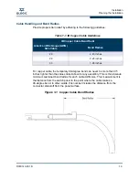
Страница 11: ...assembly This is the absolute minimum sustained bend radius for each cable AWG size This measurement is the distance from the switch panel to the point where the cable makes a 90 degree bend In other...

Страница 12: ...the numbers together to get VA Add the VA from each piece of equipment together to find the total VA requirement Then add 30 to determine the minimum amperage requirements for the UPS Transition time...

Страница 13: ...ack Tools and Equipment Required An ESD wrist strap A 2 Phillips screwdriver An M6 HEX nut wrench Pen felt tip to mark the mounting holes Lifting device e g pallet jack for the 12800 360 and 12800 180...

Страница 14: ...binet when the lower half is empty Mark the Rack Allow enough vertical space in the rack for each specific switch installation 1 Determine the location in the rack of the bottom of the switch 2 Mark t...

Страница 15: ...6 32 screws M6 cage nuts M6 screws Installation 1 Install the hat rails on each side of the switch using three 3 6 32 screws per rail Torque screws to 8in lb A typical installation is shown in Figure...

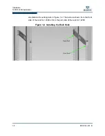
Страница 16: ...00 Installation 1 8 D000140 001 B S orientation of mounting rails in Figure 1 4 The rails are shown from the front side of the rack for 12300 or from the port side of the rack for 12200 Figure 1 4 Ins...

Страница 17: ...300 Four Post Standard Rack Mounting 12200 Four Post Shallow Depth Rack Installation In a shallow depth rack the distance between the front and back mounting posts is 16 400mm Mounting rails for the 1...

Страница 18: ...port side of the switch Fasten with three 3 6 32 screws per rail Torque screws to 8in lb Figure 1 6 12200 Hat Rails 2 Install six 6 cage nuts into the rack posts Two cage nuts into posts on the front...

Страница 19: ...two C brackets in the rear of the rack Fasten to the rack posts with four 4 M6 screws Slide the switch from the front of the rack into the C brackets and fasten to the front posts with two 2 M6 screw...

Страница 20: ...etween the front and rear rack posts Mounting Hardware Kit Contents NOTE The mounting kit contains all of the necessary parts for installing and mounting the switch into a 19 4 post server rack with a...

Страница 21: ...llation Tasks 1 Install the clip nuts Install M6 clip nuts in the following locations on EIA rails Figure 1 8 Clip Nut Installation Locations For improved stability orient the clip nuts as shown i e o...

Страница 22: ...ation 3 Orient the chassis such that mounting flanges are in the front of the rack Install the chassis in the rack Fasten chassis to the rack with four 4 M6 screws Torque to 30in lb WARNING To avoid i...

Страница 23: ...Installation 12800 040 Installation D000140 001 B 1 15 A Figure 1 11 Rack Installation 5 If applicable replace the door s on the rack...

Страница 24: ...th a distance between front and rear rack posts ranging from 28 33 711mm 838mm Mounting Hardware Kit Contents NOTE The mounting kit contains all of the necessary parts for installing and mounting the...

Страница 25: ...cable remove the doors of the rack 2 Install the clip nuts Install M6 clip nuts in the following locations on EIA rails Figure 1 12 Clip Nut Installation Locations For improved stability orient the cl...

Страница 26: ...U or 6U location This locates the chassis approximately 12 from the floor and allows the chassis to be moved onto the support rails by sliding off of the pallet 3 Install support rails in the rack Fas...

Страница 27: ...2 rear mounting Hat Brackets on the chassis and fasten with 8 32 screws There are four 4 screws per bracket Torque to 30in lb Figure 1 15 Hat Bracket Installation 5 Orient the chassis such that mounti...

Страница 28: ...ly loaded Use a mechanized lift whenever possible For a manual lift unload the product FRUs to minimize the weight Use a team of people appropriate to the weight of the product and in conjunction with...

Страница 29: ...Installation 12800 120 Installation D000140 001 B 1 21 A 6 Fasten the chassis to the rack with eight 8 M6 screws Torque to 30in lb Figure 1 17 Chassis Installation...

Страница 30: ...Installation 12800 120 Installation 1 22 D000140 001 B S 7 Slide two 2 C brackets over the Hat brackets that are pre installed on the chassis Figure 1 18 C Bracket Installation...

Страница 31: ...000140 001 B 1 23 A 8 If applicable install the optional cable management guides Fasten to the EIA rails with M6 screws Torque all screws to 30in lb Figure 1 19 Cable Management Installation 9 If appl...

Страница 32: ...d switch capable of supporting up to 432 InfiniBand ports operating at QDR speed It is designed for installations in standard width 19 mount server racks total width of a rack is typically 24 However...

Страница 33: ...000140 001 B 1 25 A 1 If applicable remove the doors of the rack 2 Install M6 clip nuts in the following locations on EIA rails for U5 installation For U6 installation increment clip nut locations by...

Страница 34: ...Installation 12800 180 Installation 1 26 D000140 001 B S For improved stability orient the clip nuts as shown i e orient the flanges horizontally Figure 1 21 Clip Nut Orientation...

Страница 35: ...n 12800 180 Installation D000140 001 B 1 27 A 3 Install support rails in the rack Fasten with two 2 M6 screws per EIA rail to pre installed clip nuts and torque to 30 in lb Figure 1 22 Support Rail In...

Страница 36: ...r 4 rear mounting brackets to the chassis and fasten with 8 32 screws There are four 4 screws per bracket Torque to 30in lb Figure 1 23 Flat Bracket Installation 5 Orient the chassis such that mountin...

Страница 37: ...lift manually Use a mechanized lift only If a manual lift is necessary first unload all field replaceable units FRUs to minimize weight Use a team of people appropriate to the weight of the product a...

Страница 38: ...llation 1 30 D000140 001 B S 6 Fasten the mounting flanges using M6 screws to the clip nuts that are pre installed in the rack There are six 6 screws per mounting flange Torque to 30in lb Figure 1 24...

Страница 39: ...Installation 12800 180 Installation D000140 001 B 1 31 A 7 Slide four 4 C brackets over the HAT brackets that are pre installed on the chassis Figure 1 25 U Bracket Installation...

Страница 40: ...D000140 001 B S 8 If applicable install the optional cable management guides Fasten to the EIA rails with M6 screws Torque all screws to 30in lb Figure 1 26 Cable Management Guide Installation 9 If a...

Страница 41: ...0 series of switches capable of supporting up to 864 InfiniBand ports operating at QDR speed To facilitate installation and management of such a large number of cables the 12800 360 switch was designe...

Страница 42: ...Installation 12800 360 Installation 1 34 D000140 001 B S Figure 1 27 12800 360 Front and Rear Cabling...

Страница 43: ...te enough space in the front of the rack to route 300 cables the two front rails should be recessed 135mm from the front of the rack The rear EIA rails should be positioned such that the distance betw...

Страница 44: ...te the chassis approximately 12 from the floor and will allow the chassis to be moved onto the support rails by sliding off the pallet 1 Install clip nuts If applicable remove the doors of the rack In...

Страница 45: ...ient the flanges horizontally Figure 1 30 Clip Nut Orientation 2 Attach four 4 mounting brackets to the support shelf as shown in Figure 1 31 Align the brackets with B marks on a support shelf and fas...

Страница 46: ...ation 12800 360 Installation 1 38 D000140 001 B S 3 Attach the support bracket to the support shelf and fasten with seven 7 10 32 flat head screws Torque screws to 30in lb Figure 1 31 Support Shelf As...

Страница 47: ...l the support shelf into the rack Fasten the M6 screws to pre installed clip nuts and torque to 30 in lb There are three 3 screws per mounting bracket Figure 1 32 Attaching the Support Shelf to the Ra...

Страница 48: ...Installation 12800 360 Installation 1 40 D000140 001 B S WARNING To avoid injury do not lift manually Use a mechanized lift only Chassis only 90kg 197lbs Fully loaded 244kg 535lbs...

Страница 49: ...e chassis has been packaged on sliding surfaces to facilitate installation in a rack by sliding off of the pallet and on the support shelf Remove the rear foam block to expose sliding surfaces The rea...

Страница 50: ...Orient the chassis on a pallet in front of the rack as shown Chassis rear should be facing front of the rack For installations in racks arranged in rows distance between adjacent rows of racks width o...

Страница 51: ...sis is at or slightly higher than the top surface of the support shelf pre installed in the rack Lock the pallet jack wheels Use a group of people to push the chassis from the front to slide it off th...

Страница 52: ...ive 5 M6 screws Fasten to the support shelf with seven 7 10 32 screws Torque to 30 in lb Figure 1 36 Fasten the Chassis to the Front of the Rack 10 Fasten the rear of the chassis to the rack Fasten th...

Страница 53: ...Installation 12800 360 Installation D000140 001 B 1 45 A Figure 1 37 Fasten the Chassis to the Back of the Rack...

Страница 54: ...rear EIA mounting rails and fasten with M6 screws to the pre installed clip nuts The guides should be installed such that the wireframe supports line up with the chassis leaf module slots There are fo...

Страница 55: ...and Ethernet ports on the 12200 12300 and 12800 series For the 12200 and 12300 these are located on the switch IB port side For the 12800 series these are located on the Serial Ethernet Chassis EEPROM...

Страница 56: ...few feet on the cable and twist the bulk cable to allow the connector to rotate to the proper orientation Doing this prevents all of the rotational forces from acting right at the connector terminatio...

Страница 57: ...t For users assembling their own cable refer to Appendix C for serial port pinout information The settings for the terminal emulation device should be 8 data bits no parity bits 1 stop bit 57 6K baud...

Страница 58: ...should be 8 data bits no parity bits 1 stop bit 57 6K baud Use VT100 emulation Flow control XON XOFF 3 If using Telnet or SSH access the switch with the following command open 192 168 100 9 4 The sys...

Страница 59: ...ed switch will have multiple unique IP addresses The default IP addresses are 12800 040 Chassis 192 168 100 9 Management Module 201 192 168 100 10 Management Module 202 192 168 100 11 12800 120 Chassi...

Страница 60: ...boot prompt type the following moduleip NEW IP ADDRESS Then press Enter NOTE For versions previous to 5 0 2 use the command spineip NOTE This command changes the IP address for image1 and image2 on ea...

Страница 61: ...For example to combine ports 2 and 20 1 Log into the switch CLI with the login admin and password adminpass 2 Enable port 2 with a command similar to ismPortSetWidth Cable02 7 bounce and press Enter...

Страница 62: ...42 where both ports of the DUO have LEDs on Figure 1 42 8X Ports Enabled 6 From the Chassis Viewer main menu click on Port Stats then IB Port Stats to display the IB Port Statistics screen The 8X port...

Страница 63: ...c For ports 19 through 24 DUOs are made by combing the ports sequentially i e port 19 and port 20 port 21 and port 22 and port 23 and port 24 Figure 1 44 12800 Leaf Module 8x DUOs For example to combi...

Страница 64: ...h 5 After reinserting the cables bring up Chassis Viewer The 8X ports are displayed as shown in Figure 1 45 where both ports of the DUO have LEDs on Figure 1 45 8X Ports Enabled 6 From the Chassis Vie...

Страница 65: ...llation Bringing Up the System For the First Time D000140 001 B 1 57 A The first port of the group port 8 is shown as active and Up while the other port in the DUO port 17 is displayed as down and Dis...

Страница 66: ...uires some attention which could indicate one of the following conditions The switch temperature is at a warning level on the module Theswitchsilicontemperatureis at awarning level approximately 90deg...

Страница 67: ...o light the LED The chassis status LED is Amber when the system can no longer function properly and indicates one of the following conditions No functional fan trays are present No functional spines a...

Страница 68: ...on Component LEDs 1 60 D000140 001 B S MRL Active The MRL Active LED is Green when mechanical release latch MRL thumbscrew is secured to the Serial Ethernet Chassis EEPROM Board SEEB Figure 1 48 MRL A...

Страница 69: ...ndications On the logical link is up port is in the Active state Off the physical link is down port is in the Down state Module Status The status LED indicates one of the following conditions Steady G...

Страница 70: ...system will take the appropriate actions to ensure that no damage is done to its components Blinking Amber once every four seconds LED test state Spine Module Figure 1 50 Spine Module LEDs Double Spin...

Страница 71: ...one to its components Blinking Amber once every four seconds LED test state SEEB Module Figure 1 51 SEEB Module LEDs RJ45 LEDs The RJ45 connectors have two LEDs Act and 100 The 100 LED is Green when a...

Страница 72: ...tus The status LED indicates one of the following conditions Steady Green the module is operating normally Blinking Green LED test state Off module is in the removable state Attention The Attention LE...

Страница 73: ...t state RJ45 LEDs The RJ45 connectors have two LEDs Act and 100 The 100 LED is Green when a 100Mbps link is connected The Act LED is Green when an Ethernet link has been established and blinking when...

Страница 74: ...d has fallen below the minimum allowed RPM for a fan Power Supply LEDs Figure 1 54 12800 Power Supply LEDs Each power supply has three LEDs DC OK AC OK and Alarm Following are the status definitions f...

Страница 75: ...icense Key If purchased certain packages of the InfiniBand Fabric Suite entitle the user to the switch based QLogic Fabric Manager Refer to the licensing documentation that comes with the InfiniBand F...

Страница 76: ...al number 2 Go to the QLogic Feature Activation License Key web site http lk qlogic com Figure 1 56 License Key Activation Center 1 3 Enter the InfiniBand Fabric Suite serial number Click Continue The...

Страница 77: ...tallation Switch Based QLogic Fabric Manager License Key D000140 001 B 1 69 A 4 Click Activate License Key and click Continue The following screen is displayed Figure 1 58 License Key Activation Cente...

Страница 78: ...ased QLogic Fabric Manager License Key 1 70 D000140 001 B S 5 Enter your email address in the Email and Confirm Email text boxes Click Continue The following screen is displayed Figure 1 59 License Ke...

Страница 79: ...s click on the flashlight hyperlinks The following is displayed Figure 1 60 License Key Activation Center 5 7 In the City and Zip text boxes enter the applicable information and click Search Alternati...

Страница 80: ...nstallation Switch Based QLogic Fabric Manager License Key 1 72 D000140 001 B S 8 If the information is correct click Close The following screen is displayed Figure 1 62 License Key Activation Center...

Страница 81: ...text box enter the FRU GUID of the following applicable components QLogic 12300 chassis QLogic 12800 series Management Module to be used as the master subnet manager Master and redundant switch based...

Страница 82: ...ewer the View FRU button for each applicable chassis or module FRU For the12300 via the switch Command Line Interface CLI using the command showIBNodeDesc For the 12800 series via the switch Command L...

Страница 83: ...ers can order a six port License Key upgrade for the QLogic 12300 BS18 advanced 40Gb s QDR InfiniBand switch Refer to the licensing documentation that comes with the QLogic 12300 BS18 switch for instr...

Страница 84: ...ck Continue 6 Enter all applicable contact information Click Continue 7 Enter the transaction code and switch GUID then click Continue NOTE The FRU GUID can be found On the label of each 12300 BS18 sw...

Страница 85: ...nical Commission IEC 297 These racks are commercially available in various depths It is recommended to use rack with minimum of 36 depth to facilitate cable installation and routing Other physical att...

Страница 86: ...and Thermal Management Cooling Air cooled with a hot plug fan power tray three fans per tray 40mm 12VDC 12300 Four fans no fan trays 12200 Front to back airflow NOTE The 12200 also offers a reversed...

Страница 87: ...ommended that the 120 180 and 360 be installed as follows Intake fan side towards the cold aisle Exhaust fan side towards the hot aisle Thermal management Temperatures of all major heat producing comp...

Страница 88: ...er supplies are are N 1 redundant and hot pluggable NOTE An AC power cord is required for each power supply Refer to the table below Table A 3 System Power Attributes Model 12800 360 12800 180 12800 1...

Страница 89: ...A Maximum current per supply 100Amps Inrush Current 30Amps Max Power Factor efficiency 99 230V full load Power Inlet connector IEC320 C20 of Power Inlets 12 6 4 4 Power Cord connector IEC320 C19 Table...

Страница 90: ...ere rating limit of the power outlet power strip or an extension cable that the equipment is plugged into As such the power delivery system must be that the power supplies do not overpower the maximum...

Страница 91: ...e Germany Greece Hungary Indonesia The Netherlands Norway Poland Portugal Russia Spain Sweden International 200 240 IEC 309 3 wire two phase earth Connector size and color variations are used to indic...

Страница 92: ...QLogic 12000 Series Product Specifications 12800 Series A 8 D000140 001 B S Notes...

Страница 93: ...der hetrisicoop eenelektrischeschok door alle stroomkabelsloste koppelen voordat u onderhoud pleegt aan de eenheid Varoitus 1 Irrota laite Yksik ss saattaa olla useampia kuin yksi virtajohto Irrota ka...

Страница 94: ...imenta o Para reduzir o risco de choque el ctrico desligue todos os cabos de alimenta o antes de fazer a manuten o da unidade Declaraci n 1 Desconexi n de dispositivo Esta unidad puede tener m s de un...

Страница 95: ...llettavien ohjeiden mukainen m r henkil it K yt mekaanista nosturia aina kun se on mahdollista D claration 2 Soulever le ch ssis Employez des mesures de s curit pour soulever REMARQUE Faites appel au...

Страница 96: ...ci n 2 Elevaci n del chasis Observe las pr cticas de seguridad cuando quiera elevar el chasis NOTA utilice un grupo de gente apropiado al peso de cada producto especificado junto con las pautas que co...

Страница 97: ...Safety and Regulatory Compliance Information Safety Information D000140 001 B 5 A 2...

Страница 98: ...ux cartes de circuits imprim s Anweisung 3 Gefahr vor elektrischem Schock Um der Gefahr vor elektrischem Schock vorzubeugen halten Sie H nde und Finger den Netzteilsch chten und der R ckwand fern Dich...

Страница 99: ...f r elektrisk st t Reducera risken f r elektrisk st t genom att h lla h nder och fingrar borta fr n str mf rs rjningsfack och bakpanelsomr den Kijelent s 3 ram t s vesz lye Az ram t s kock zat nak cs...

Страница 100: ...r une exposition un rayonnement laser dangereux Ce rayonnement peut provenir des connecteurs ou des c bles en fibre optique Anweisung 4 Laserstrahlung manche optischen Produkte geben Laserstrahlung ab...

Страница 101: ...nectores o cables de fibra ptica Uttalande 4 Laserstr lning Vissa optiska produkter kan uts nda laserstr lning Borttagning av skydd kan resultera i exponering f r riskfylld laserstr lning Str lning ka...

Страница 102: ...carte de circuits imprim s Ne retirez pas les capots Anweisung 5 Wartung nur durch Fachmann m glich Gef hrlich hohe Stromst rken sind in Netzteilen und in den Modulen der Busleiterplatte vorhanden En...

Страница 103: ...erh llas av anv ndaren Farliga energiniv er kan finnas i str mf rs rjningsenheter kretskortmoduler Ta inte bort skydd Kijelent s 5 A berendez s nem tartalmaz felhaszn l ltal jav that alkatr szeket Ves...

Страница 104: ...nweisung 6 Ger teinstallation Die Installation Entfernung oder Erneuerung von Geh use und Modulen sollte nur durch Fachpersonal erfolgen Dichiarazione 6 Installazione dell apparecchiatura Solo il pers...

Страница 105: ...y Compliance Information Safety Information D000140 001 B 13 A Kijelent s 6 Berendez s telep t se Kiz r lag szakk pzett szem lyzet sz m ra megengedett a burkolat vagy a modulok telep t se elt vol t sa...

Страница 106: ...h iri it EMI ja pit v t yll j hdytysilman tasaista jakautumista koteloon D claration 7 Ajouter ou remplacer des modules Ces modules sont con us exclusivement pour une installation avec des unit s de...

Страница 107: ...7 Agregar o sustituir m dulos Estos m dulos solamente se pueden instalar en unidades de base de la serie QLogic 12000 Siempre instale protectores al retirar un m dulo activo Los protectores previenen...

Страница 108: ...Safety and Regulatory Compliance Information Safety Information B 16 D000140 001 S 7 QLogic 12000 MPFD EMI...

Страница 109: ...Safety and Regulatory Compliance Information Safety Information D000140 001 B 17 A...

Страница 110: ...Safety and Regulatory Compliance Information Safety Information B 18 D000140 001 S Notes...

Страница 111: ...D000140 001 B C 1 C Serial Port Pinouts For those users making their own serial cables follow the guidelines below Figure C 1 Serial Port Pinouts...

Страница 112: ...ort signals are NOT used Please see Table C 1 for a list of RJ45 on Digi to RJ11 cross references The cable should connect the three RJ45 signals on the Digi to the RJ11 connector The signals for the...

Страница 113: ...Serial Port Pinouts D000140 001 B C 3 A...

Страница 114: ...Serial Port Pinouts C 4 D000140 001 B S Notes...

Страница 115: ...integrity QLogic 12200 NOTE For an externally managed 12200 refer to the Fast Fabric User Guide for update information Chassis Replacement FRU part number Standard chassis 12200 BS01 Reversed airflow...

Страница 116: ...d Serial cables Set these aside for reinstalling the replacement switch 3 Remove the switch from the rack Keep all rail hardware installed in the rack 4 Remove the hat rails from the switch Set these...

Страница 117: ...val Procedures 1 Push the finger tab to the right 2 While holding the finger tab pull the module handle to disengage the unit from the switch Figure D 1 12300 Fan Power Module Removal Replacement Proc...

Страница 118: ...2800 Series Fan Replacement FRU part numbers Intake Fan 12800 FITK Exhaust Fan 12800 FEXH Removal Procedures 1 While holding the handle push the release latch to the right Figure D 2 12800 Fan Removal...

Страница 119: ...xhaust fan by checking the FRU label or noting the location of the open notch Figure D 3 12800 Intake and Exhaust Fans Replacement Procedures 1 Slide the fan tray straight into the open slot until it...

Страница 120: ...s and are not intended to be sold separately Removal Procedures 1 Push the release latch to release the arm Figure D 4 12800 Power Removal 2 Carefully pull the supply until it is disengaged from the c...

Страница 121: ...rocedures NOTE If the leaf module is in one of the chassis management slots the mechanical release latch MRL must be moved in order to remove the leaf To move the MRL loosen the thumbscrew attached to...

Страница 122: ...the backplane connector Figure D 6 12800 Leaf Removal 2 Carefully pull the module out of the chassis Replacement Procedures 1 Slide the module straight into the open slot until it engages with the bac...

Страница 123: ...the release arms out until the spine module disengages from the backplane connector Figure D 7 12800 Spine Removal 2 Carefully pull the module out of the chassis Replacement Procedures 1 Slide the mo...

Страница 124: ...anagement module disengages from the backplane connector Figure D 8 12800 Management Module Removal 3 Carefully pull the module out of the chassis Replacement Procedures 1 Slide the module straight in...

Страница 125: ......

Страница 126: ...mation supplied by QLogic Corporation is believed to be accurate and reliable QLogic Corporation assumes no responsibility for any errors in this brochure QLogic Corporation reserves the right without...

Отзывы: