background image


Emergence PRO

 3D Printer Manual 


Revision C 

/

 December 2020 

Page 47 of 68 


5.


Once 

Open

 is selected, the file will be uploaded to the printer and the print will 

begin. This file will be saved on Card 0, which is inserted into the printer controller. 


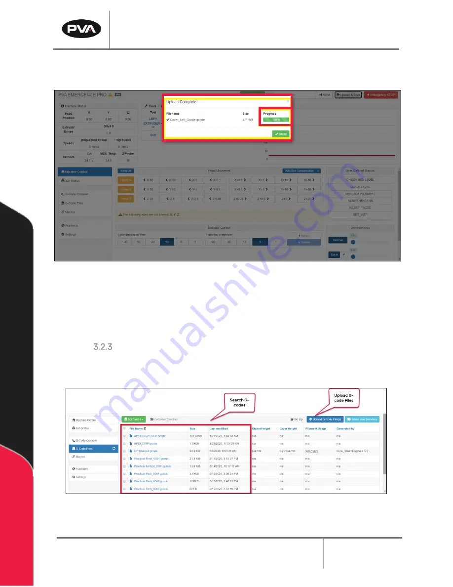
Figure 52: Upload Complete 

A status bar will show the progress of the G-code file upload as it is being transmitted 
wirelessly to the printer. Once the file has been successfully uploaded, the printer will 
begin the print sequence for the selected G-code. 


G-code Files 

G-Code Files allows for G-code files to be uploaded, downloaded, deleted and sorted into 
sub directories.  


Figure 53: G-code Files 


Содержание Emergence PRO

Страница 1: ...Emergence PRO 3D Printer Operation Manual Revision C INNOVATION PRECISION EXCELLENCE ...

Страница 2: ...olders of this document with respect to changes subsequently made Precision Valve and Automation Inc makes no representation or warranty expressed implied or statutory with respect to and assumes no responsibility for the accuracy completeness sufficiency or usefulness of the information contained herein No warranties of merchantability or fitness for purpose shall apply This document including th...

Страница 3: ... the Printer 13 Setting Up the Emergence PRO Wireless Connection 15 Connect Web Interface to Existing Network 17 M587 Command 18 Change Web Interface to Client Mode 20 Emergence PRO Setup 24 Printer Tool Kit 24 Check Levelness of the Bed Relative to the Gantry 25 Adjust Bed Level 27 Check Bed Levelness 29 Install and Gap Hot End 31 Remove Hot End 36 Load Filament 36 Unload Filament 39 Perform Test...

Страница 4: ...es 50 Filament 50 Hot End 50 Print Bed 50 Printer 50 Cleaning and Maintenance 51 Hot End Cleaning and Maintenance 51 Rail Maintenance 51 Belt Maintenance 51 Check for Quality 52 Quality Checklist 52 Quick Tips 54 Changing Print Speed 54 Changing Flow Rate 54 Troubleshooting 55 Probe Failed to Extend 55 Probe Failed to Trigger Error 55 Probe Unexpectedly Triggered Error 55 Under Extrusion 55 Over E...

Страница 5: ...Materials Errors 57 APPENDIX A 58 Printing Terminology 58 APPENDIX B 59 Printer Dimensions and Parts 59 X Y Assembly 60 Z Assembly 61 Print Head 61 Technical Specifications and Warnings 64 Warnings 64 APPENDIX E 65 Recommended Maintenance Schedule 65 Table of Figures 66 Warranty 68 PVA Warranty Policy 68 ...

Страница 6: ... 12047 Tel 1 518 371 2684 Fax 1 518 371 2688 Website rapidplaster pva net Email med pva net Technical Support Tel 1 844 734 0209 Email cs pva net Document History Revision Revision Date Reason for Changes REV C November 2020 Updated Getting Started and Print sections REV B July 2020 Emergence PRO v2 Updates REV A December 2019 Initial Release Note All photographs and CAD model representations in t...

Страница 7: ...perate the system read and understand the manuals provided with the unit Never put hands or tools in areas with this symbol when the machine is in operation A dangerous condition may exist Read and understand the manuals provided with the unit before any repairs or maintenance is done Only a qualified individual should do service Use caution when there are pressurized vessels Find and repair any l...

Страница 8: ...the power disconnect switch Warning notices are used to emphasize that hazardous voltages current temperatures or other conditions that could cause personal injury exist in this equipment or may be associated with its use Only qualified personnel should enter areas designated with this symbol Laser light source present Do not stare directly into the beam Do not use in the presence of highly reflec...

Страница 9: ...er Locate and define all safety labels on and around the printer before you turn the machine On Dispose of all used parts and materials in accordance with local laws and regulations Safety is a joint responsibility between the OEM and the end user All precautions and practices should be in accordance with local regulations Do Not Use incompatible tools remove door interlocks or bypass safety devic...

Страница 10: ...e 2 Open the shipping crate by first taking the lid off and then removing the sides 3 Remove plastic wrapping around the metal ramp and any additional items that may be included Figure 1 Remove Plastic Wrapping 4 Remove the four metal plates around each of the wheels by removing the lag screws using a 9 16 socket wrench Figure 2 Remove Metal Plates ...

Страница 11: ...the printer on level ground 8 To level the printer lower the feet by turning the red knob on each leg to stabilize the 3D printer Turning the knob to the left lowers the foot and turning the knob to the right raises the foot Local Ventilation Disclaimer IMPORTANT End user should consult manufacturer safety data sheets to identify if local ventilation is required for their application and proceed a...

Страница 12: ...e steps below to install the exhaust flange Remove cover from exhaust flange mount in the top rear corner of the machine Figure 4 Remove Exhaust Flange Cover Locate the 4 inch exhaust flange provided with the machine Figure 5 Exhaust Flange Install exhaust flange through top hole and secure with 4 M6X1 hex nuts Figure 6 Secure Exhaust Flange ...

Страница 13: ...side of the printer 2 Remove the key tied to the handle on the front door The key is for the back door 3 Open the front door and remove the green metal bracket holding the extruder in place by removing the mounting screws Figure 7 Remove Bracket from Front Door 4 Remove the two green brackets attached to the print bed Figure 8 Remove Brackets from Print Bed ...

Страница 14: ...ision C December 2020 Page 14 of 68 5 Unbox the nozzle brush from the box that is shipped with the printer Figure 9 Nozzle Brush Box 6 Install the nozzle brush in the hole on the front left of the print bed Figure 10 Install Nozzle Brush ...

Страница 15: ... wireless network connection capability that allows you to use the printer remotely with a computer For the initial setup of the printer you will need to use this feature 1 Turn on the printer using the on off switch located near the power cord connection Figure 11 The printer control screen will start up on its own 2 Via a laptop or PC connect to the network matching your printer serial number by...

Страница 16: ...pper right corner of the back panel of the printer Figure 13 Serial Number 4 The password for the network is PVA12345 This should not be needed next time you connect 5 Once connected to the network open Google Chrome web browser and type 11 22 33 44 into the address bar This will bring you to the web interface Figure 14 Web Interface ...

Страница 17: ...ption is not compatible with 5 GHz networks 1 Reserve a dedicated IP address with your IT team or via your router The process to do this will be specific to your network hardware and you may need consult the manufacturer 2 Use the steps outlined in Section 2 3 2 to connect to the Emergence PRO s WiFi network 3 Once connected access the Web Interface 4 Navigate to the G Code Console Figure 15 G cod...

Страница 18: ...nnected to this network optional o This should be the IP address that you previously reserved o If zero is entered or not specified an IP address will be acquired via DHCP This will result in your network hardware assigning the available IP addressed based on existing devices connected to the network The M587 command must be written in the following format M587 S WIFI_NETWORK_NAME P PASSWORD Ix xx...

Страница 19: ...ed by the printer if formatted correctly you will see the M587 shown in green within the system messages Figure 16 Enter M587 Command Additional Commands To view stored networks enter M587 To see the current network connection and IP enter M552 To remove the network from memory enter M588 S NETWORK_NAME To remove all networks from memory enter M588 S ...

Страница 20: ... stop 4 If printer does not connect to the network confirm network credentials network strength and frequency To revert the printer back to host mode select the Set Wi Fi Host Mode macro to return the unit to host mode To view printers current network status the M552 command can be entered in the console tab of the HMI Set Printer Wi Fi to Start in Client Mode 5 To switch the web interface network...

Страница 21: ...micolon must be placed in front of the network and removed from the other networks Figure 18 Edit Config g File 9 Delete the semicolon from M552 S1 10 Add a semicolon to M552 S2 to select the network Figure 19 Change Network 11 Click Save Changes Note The web interface must be rebooted after changes to the network have been made ...

Страница 22: ...reboot the web interface Figure 20 Reboot Confirmation 13 The web interface will confirm the file was successfully updated Figure 21 File Updated 14 The control screen on the Emergence PRO will confirm that the machine is connected to the network Figure 22 Network Connection Confirmation ...

Страница 23: ...web interface The green popup will disappear after 10 seconds Figure 23 Control Screen WiFi Confirmation Note The Emergence PRO can also be powered down so the SD card storing the config g file can be removed from the controller Within the system file of the SD card is the Config g file This file can be opened and modified with a program editor such as Notepad ...

Страница 24: ...cate the Tool Kit included with your printer The following items are included and shown below Figure 24 Printer Tool Kit 1 Roll of blue tape 2 Toolbox 3 Spray adhesive 4 Lubricant 5 Hex wrenches 6 Shimmy 7 Side cutters 8 Cleaning needles 9 SD card and converter 10 Tweezers 11 Brass wire brush 12 Open ended wrench 9 16 inch 13 Spade Putty knife ...

Страница 25: ...Rotate Emergency Stop button clockwise to release To undo Halted status in the web interface reconnect to the network 3 On Printer Control Screen select Quick Level on the right side of the display Figure 25 4 The print head will move to the rear right of print bed The Print head will move to the center of the bed extending the profile probe The bed will move upwards until the probe sensor is trip...

Страница 26: ...first value will be for the rear right leveling screw This will typically be 0 o The second value will be the amount of adjustment required for the left leveling screw 0 15 turn up 0 10 mm in Figure 26 o The third value will be the amount of adjustment required for the front right leveling screw 0 04 turn down 0 03 mm in Figure 26 Figure 26 Leveling Values Displayed ...

Страница 27: ...ustments are needed loosen the hex nut on the left and front right leveling screw on the bottom of the bed with a 7 mm wrench Figure 28 The tools are included in the Printer Tool Kit Note The back right adjustment screw does not need to be adjusted Figure 27 Three Leveling Screws Figure 28 Hex Nut ...

Страница 28: ...tion of the screw 3 With a 2 mm hex wrench move the screw up or down by rotating the leveling screw To move the screw up rotate clockwise To move the screw down rotate counter clockwise Figure 29 Rotate Leveling Screw 4 After adjusting the leveling screws the appropriate amount re run the Quick Level macro to see if any additional adjustments are needed o If results require less than a 0 12 turn a...

Страница 29: ...g initial setup or if the printer is moved Check Bed Levelness 1 To check the levelness of the bed after running the Quick Level macro or at any time run the Check Bed Level macro The printer will home Check the height of 4 corners of the build plate 2 On Printer Control Screen select Check Bed Level on the right side of the display Figure 30 3 The print head will move to rear right of print bed t...

Страница 30: ...d Compensation Figure 31 and select Show Mesh Grid Heightmap Figure 31 View Results via Web Interface Figure 32 Top View 6 Orient the origin in the graphical interface by left clicking in the grid area and dragging your mouse The origin should be in the front left corner with the red arrow X axis pointing right and the blue arrow Z axis pointing up to match the printer coordinate system ...

Страница 31: ...our points Figure 32 8 If adjustments are needed re run the Quick Level macro and follow instructions to level the bed Section 2 4 2 Install and Gap Hot End 1 On Printer Control Screen select Move The Move Head screen will display 2 In the Z value field press 50 twice to lower the bed roughly 100 mm to install the hot end A positive move will increase the gap between the hot end and the print bed ...

Страница 32: ...s should face the front and the blue cables should be accessible Ensure it is fully seated and pushed up as high as possible into the opening Figure 34 Inserting Hot End Note The hot ends are labeled based on nozzle size and material as follows Hot End Label Nozzle Size and Material 0 4B 0 4 mm Brass Nozzle 0 6B 0 6 mm Brass Nozzle 2 0B 2 0 mm Brass Nozzle 2 0SS 2 0 mm Stainless Steel Nozzle 3 0B ...

Страница 33: ...ly inserted and bottomed out within the hot end 7 Plug in the white Heater Cartridge Connector into the slot labeled C 8 Plug in the blue Thermistor Connector into the slot labeled D Note If the thermistor connector is not plugged in correctly the Active Temp sensor will read 2000 C In that case correctly insert the thermistor connector and press Reset Heaters on the Printer Control Screen ...

Страница 34: ...ve hot end temperature will not accept new parameters or heat up while the tool icon is active 12 On Printer Control Screen set the active hot end temperature to the appropriate print temperature for the filament you will use by selecting the Active Temp icon 13 Enter the desired temp and press Set 14 Select the Hot End icon o The current temperature button will turn pink when it is heating the ho...

Страница 35: ...Tool Kit between the bed and the nozzle 18 Physically lower the hot end height until it just touches the 0 2 mm shim WARNING When moving the hot end hold the coil part of the hot end Do not hold the hot end enclosed in red plastic The hot end and print bed are HOT 19 Tighten the red Hot End Clamp handle to lock the hot end into position 20 Twist the red clamp handle until you feel enough tension C...

Страница 36: ...End Temperature Nozzle PCTG 95C C 240 C Brass FlexyFit 40 C 235 C Brass PLA 65 C 210 C Brass Nylon 12 85 C 285 C Stainless Steel PLA Carbon Fiber 70 C 210 C Stainless Steel Figure 37 Temperatures for Installing Filament 3 Slide the appropriate filament onto the filament support roller The filament roll should be oriented so the filament will be coming off the top of the roll toward the front of th...

Страница 37: ...Emergence PRO 3D Printer Manual Revision C December 2020 Page 37 of 68 Figure 38 Filament Load Figure 39 Shaft Collars ...

Страница 38: ...rial will be pulled from the roll If this is not occurring manually feed material from the roll to ensure it has reached the extruder 9 After the initial 200 mm is fed extrude another 100 mm at a slower speed less than 20 mm s until material is freely flowing through the nozzle The example below reflects a speed of 10 mm s In Extrusion Amount press 100 once In Speed select 10 Press Extrude 10 Wipe...

Страница 39: ...o the appropriate print temperature for material 3 Via the Extrusion button on the printer display extract roughly 300 mm of filament to clear the extruder Set Extrusion Amount to 100 Set Speed to 50 Press Retract three times 4 Once filament is retracted manually wind up the filament spool until the filament is free from the filament guide Perform Test Prints 1 On Printer Control Screen press File...

Страница 40: ... 2020 Page 40 of 68 2 Select Test Prints Figure 42 Figure 42 Test Print Files 3 The test prints loaded onto Card 0 which is part of the Printer Control Screen will be listed Select a test print for the filament loaded and hot end installed Select Print ...

Страница 41: ...omes the print head in all axes or in an individual axis Auto homing button on the far left X axis button in the middle left Y axis button in the middle right Z axis button on the far right 9 Bed Probe Probes bed and creates bed level profile 10 File Selection Displays available prints 11 Move Selection Allows movement of print head X axis negative moves left positive moves right Y axis negative m...

Страница 42: ...trol screen 15 Print Screen Similar to the control screen and only used when printing Allows for pause resume and cancel commands 16 Console Screen Displays codes and commands recently entered in the printer 17 Setup Screen Options for adjusting the touchscreen display settings Figure 43 Printer Control Screen ...

Страница 43: ...ither option MicroSD 1 Copy the G code file from your PC to a MicroSD card Note You may need to insert the microSD card into an adapter The micro SD card will typically show up as drive D Figure 44 MicroSD Card 2 Insert the MicroSD card into the SD card reader located on top rear of machine next to Wi Fi antenna Note The MicroSD card must be inserted with the metallic contacts facing the center of...

Страница 44: ...68 3 Press the MicroSD card button on the Printer Control Screen Figure 46 MicroSD Button 4 On the MicroSD screen press the MicroSD card icon to switch between the onboard SD card Card 0 and the secondary SD card on the top of the machine Card 1 Figure 47 MicroSD Screen ...

Страница 45: ...Emergence PRO 3D Printer Manual Revision C December 2020 Page 45 of 68 5 Select a desired G code to run Figure 48 Select G code 6 Select Print Figure 49 Print ...

Страница 46: ... via the Web Interface Section 2 3 2 2 To upload a new file from the Web Interface click Upload Start in the upper right hand corner of the Web Interface Home Screen Figure 50 Emergence PRO Web Interface Home Screen 3 When prompted select the desired G code to print 4 Select Open Figure 51 Select G code and Open ...

Страница 47: ...to the printer controller Figure 52 Upload Complete A status bar will show the progress of the G code file upload as it is being transmitted wirelessly to the printer Once the file has been successfully uploaded the printer will begin the print sequence for the selected G code G code Files G Code Files allows for G code files to be uploaded downloaded deleted and sorted into sub directories Figure...

Страница 48: ...ame or delete the file as well as manually edit the G code Figure 54 G code Right Click Options Run Test Prints To run test prints preloaded on your printer follow the steps below 1 Load the appropriate hot end and filament used to print the selected test print 2 On Printer Control Screen press File Selection button 3 Select Test Prints and select one of the test prints 4 Press Print Run G Codes T...

Страница 49: ...tice that filament is not being extruded consistently or that the printed filament is cloudy it may indicate that you have improper tension on the extruder or that the filament is saturated with moisture Paying attention to the next layers will help you save filament and identify any issues with your print Opening the Door and Pausing the Print If you need to access the print you should always pau...

Страница 50: ...eat the hot end only when working on the printer or when the printer is fabricating a print Filament should not be left in the hot end when the printer is not in use Leaving filament in the hot end can lead to clogs and jams In addition leaving filament in the hot end may expose the filament to humid air which will affect the quality of the print Print Bed Before each print it is recommended to ca...

Страница 51: ...l amount of lubricant directly to the grooves in the rails Use the control screen to move the extruder assembly along the entire length of each axis Note The z axis screw should also be lubricated Belt Maintenance The Emergence PRO uses a single belt for moving along the X Y axis While testing is performed on the Emergence PRO before shipping it is recommended that the belt be examined before use ...

Страница 52: ...good visually however it feels like it is not well adhered to the rest of the model This is a structural concern and indicative of future complications with prints Any time the printer creates a print with delamination it should be thoroughly cleaned Missing layers This is an example of temporary under extrusion and will be considered a weak layer This can be a result of mechanical or filament iss...

Страница 53: ...Blobs and Zits These are small amounts of extra filament melted onto the product They are not a sign of structural damage and can be removed using a razor blade or grinder Be careful not to remove too much material which would sacrifice some structural integrity If this happens in excess it is a sign that the nozzle must be cleaned Poor First Layer Adhesion This is a sign that the print bed needs ...

Страница 54: ... print speed may help improve print quality and improve first layer adhesion However slowing down too much may introduce new problems such as drooping Slowing down the print speed by 5 or 10 is a good start remember that the speed is listed as a percentage Changing Flow Rate The flow is the amount of extruded material and is dictated by several factors Increasing the flow rate may help with first ...

Страница 55: ...annot move the move the Z axis via the controller the Z axis is no longer energized This will allow you to hold onto to the Z axis coupling and rotate it by hand Before manually moving an axis the operator should always engage the E stop to ensure there is no power to the motors 2 Manually pull the probe tip down and ensure nothing is binding or damaged 3 Run the Reset Probe macro option Under Ext...

Страница 56: ...print temperature to allow for extra time for heat to transfer from the heater to the build plate An approved material is being used The end of the nozzle is clean of excess material The nozzle is properly gapped to 0 2 mm The bed is level o This can be done by quickly checking the four corners with the Check Bed Level macro or run Quick Level macro The filament is dry o Consult the manufacturer f...

Страница 57: ... to the printing temperature of your chosen cold pull filament while removing the old filament Feed the cold pull filament through the nozzle until it begins to ooze out Cool the hot end while applying constant pressure on the filament strand This ensures the tip of the strand molds to the shape of the nozzle s interior while cooling When the hot end is about 60 C release the pressure By this time...

Страница 58: ...unit time G code The file type that the printer will use to print the model This file contains all the printer settings and model information needed to print Printer File Has a gcode file extension Print Speed Defines at which speed in millimeters second the print head moves while printing Profile The saved settings applied to the 3D model when slicing in a slicing software Slicer The software use...

Страница 59: ...Emergence PRO 3D Printer Manual Revision C December 2020 Page 59 of 68 APPENDIX B Printer Dimensions and Parts Figure 55 Printer Dimensions ...

Страница 60: ...Emergence PRO 3D Printer Manual Revision C December 2020 Page 60 of 68 X Y Assembly A breakdown of the X Y assembly Figure 56 X Y Assembly ...

Страница 61: ...Emergence PRO 3D Printer Manual Revision C December 2020 Page 61 of 68 Z Assembly Figure 57 Z Assembly Print Head ...

Страница 62: ...Emergence PRO 3D Printer Manual Revision C December 2020 Page 62 of 68 Figure 58 Print Head 1 ...

Страница 63: ...Emergence PRO 3D Printer Manual Revision C December 2020 Page 63 of 68 Figure 59 Print Head 2 ...

Страница 64: ... in the USA Front loading multi roll enclosed material storage Precision Aluminum build plate 5 inch touch interface with Wi Fi connectivity Filament break detection Warnings Do not use if wires are frayed connections are loose or you detect unusual conditions that could indicate a short Do not use hot end in or around water This product is designed to melt plastic During and after use parts of th...

Страница 65: ...e Dehumidifier Once per Week Check Belt Tension Once per Month Clean Hot End Every 5 prints Lubricate Rails Once per Month Replace Hot End Every 3 to 6 Months Task Frequency Date Last Performed Recharge Dehumidifier Once per Week Check Belt Tension Once per Month Clean Hot End Every 5 prints Lubricate Rails Once per Month Replace Hot End Every 3 to 6 Months ...

Страница 66: ...ure 16 Enter M587 Command 19 Figure 17 Access System Editor 20 Figure 18 Edit Config g File 21 Figure 19 Change Network 21 Figure 20 Reboot Confirmation 22 Figure 21 File Updated 22 Figure 22 Network Connection Confirmation 22 Figure 23 Control Screen WiFi Confirmation 23 Figure 24 Printer Tool Kit 24 Figure 25 Quick Level 25 Figure 26 Leveling Values Displayed 26 Figure 27 Three Leveling Screws 2...

Страница 67: ...43 Figure 46 MicroSD Button 44 Figure 47 MicroSD Screen 44 Figure 48 Select G code 45 Figure 49 Print 45 Figure 50 Emergence PRO Web Interface Home Screen 46 Figure 51 Select G code and Open 46 Figure 52 Upload Complete 47 Figure 53 G code Files 47 Figure 54 G code Right Click Options 48 Figure 55 Printer Dimensions 59 Figure 56 X Y Assembly 60 Figure 57 Z Assembly 61 Figure 58 Print Head 1 62 Fig...

Страница 68: ...d from PVA or from factory authorized dealers will void all warranties All PVA warranties extend only to the original purchaser Third party warranty claims will not be honored at any time Prior to returning a product for a warranty claim a return authorization must be obtained from PVA s customer service department Authorization will be issued either via the telephone facsimile or in writing upon ...

Отзывы: