background image

Page 33 

Stability 

The stability level is an indication of the consistency of flow reading, as derived 
from  the  combination  of  signal  strength  and  statistical  fluctuations  of  the  flow 
reading.  A high level of stability would indicate optimum condition, and relatively 
healthy  flow  within  the  channel  and  indicate  higher  levels  of  repeatability  and 
better flow tracking.  The stability does not necessarily indicate the accuracy of 
the flow reading, as this is subject to calibration.   
 

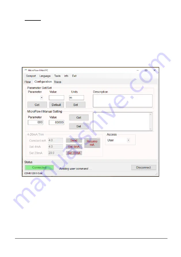
Configuration Tab 


Parameter Get/Set 

This  feature  allows  you  to  obtain  and  change  parameter  values  from  the  list 
available.  Further information of these parameters and their values can be found 
in 

Chapter 7 – Parameter Listing and Descriptions

Get: 

This will read and display the current ‘Value’ of the parameter selected, along with 
‘Units’  of  measurement  where  used,  and  a  brief  description  of  the  parameter 
selected.  Select the desired parameter from the drop down ‘Parameter’ box and 
select ‘Get’ 

Содержание MicroFlow-i

Страница 1: ...MICROFLOW INSTRUCTION MANUAL...

Страница 2: ......

Страница 3: ...made to ensure accuracy of this documentation but Pulsar Process Measurement Limited cannot be held liable for any errors Pulsar Process Measurement Limited operates a policy of constant development...

Страница 4: ......

Страница 5: ...19 Locating the MicroFlow i 19 Installing the Sensor 22 Preparation for Operation 23 General Maintenance 23 Sensor Maintenance 24 Chapter 4 Understanding how the MicroFlow i operates 27 MicroFlow i HA...

Страница 6: ......

Страница 7: ...l It is important that this manual is referred to for correct installation and operation There are various parts of the manual that offer additional help or information as shown Tips TIP At various pa...

Страница 8: ...ed by the on board microprocessor via the antenna and analysed to determine the velocity The MicroFlow i s compact and versatile design makes it easy to install and ideal for confined spaces Housed in...

Страница 9: ...enclosed plastic pipes and concrete not reinforced channels Suitable for abrasive and aggressive materials Resilient to liquid vapour wind or temperature No minimum liquid level required for measureme...

Страница 10: ...i can be mounted via a rear 1 BSP to M20 thread adapter supplied with unit The MicroFlow i is loop powered and gives a 4 to 20mA output which is proportional to the flow velocity A fault condition ala...

Страница 11: ...ity Performance Velocity Range 0 2 6 0 m s 0 66 19 7 ft s Accuracy The greater of 1 5 or 0 05 m s 0 1ft s Optimum installation Install at an angle of 45 in line with flow For more information see Loca...

Страница 12: ...Page 6 EU Declaration of Conformity...

Страница 13: ...al signal via a HART master The MicroFlow i cable is a twisted pair with an overall cable screen The twisted pair are red and black connect the red to ve and the black to the ve The screen should go t...

Страница 14: ...nsuring that the type of protection is not compromised Aggressive Substances e g such as acidic liquids or gases that may attack metals or solvents that may affect polymeric materials Suitable precaut...

Страница 15: ...screen The twisted pair is red and black connect the red to ve and the black to ve The screen should go to signal ground Typical wiring for the MicroFlow i Important Information In the case of the Ex...

Страница 16: ...SAFE AREA DUAL ZENNER BARRIER Ex ia Version 4 20mA mode DOUBLE ZENNER BARRIER CURENT SENSED IN ve Ui 28V Li 162mA Pi 1 03W V PSU SENSE HAZARDOUS AREA SAFE AREA GALVANIC ISOLATOR Ex ia Version 4 20mA...

Страница 17: ...ow i sensor is to be mounted on its own in a specific location or along with a Pulsar dBi or dB level transducer Please see Angled Mounting Bracket for dimensions of this bracket please note that the...

Страница 18: ...Page 12 Angled Mounting Bracket Part number dBA0008MF 45o Side view 176mm 22mm 22mm R20mm 12mm 100mm 90mm 130mm Top view 100mm...

Страница 19: ...ge 13 Important Information Using a spirit level ensure that the Mounting Bracket is level before attaching the sensor to the bracket R20mm 4 off 12mm 14mm 100mm 60mm 20mm 20mm 100mm 60mm 26mm Rear vi...

Страница 20: ...own below in Fig 1 and Fig 2 BOTTOM 90 mm 1 BSP 78 mm 39mm 140 mm To obtain the most accurate results ensure the device is mounted at a 45 angle to the surface being measured 45 Surface of measurement...

Страница 21: ...to the bracket This will reduce the risk of any twisting in the cable Ensure that the sensor is tightened and the dot is in the correct position Important Information When fixing the sensor to the ada...

Страница 22: ...ould be taken not to overtighten the sensor when everything is connected as seen in Fig 5 below as this could cause damage to the housing M i Central to the movement of flow in channel Fig 4 Fig 5 305...

Страница 23: ...ere the MicroFlow i is obtaining measurements following the direction of the flow or facing the direction of flow Fig 6 and Fig 7 illustrate the correct positioning of the devices according to the dir...

Страница 24: ...for ease of use when connecting the MicroFlow i to monitor flow velocity You can also use Pulsar s MicroFlow i HART PC software to interrogate and obtain readings from the device Please refer to Chap...

Страница 25: ...onjunction with the Ultimate Controller with firmware version 1 5 2 and later When a level measurement transducer is used and mounted on the same bracket as the MicroFlow i Take into account the blank...

Страница 26: ...then be positioned on a straight part of the channel at a minimum distance that is at least five times the width of the channel before a bend in order to obtain optimal velocity readings Examples of p...

Страница 27: ...Page 21 Diagram 4 Diagram 3 Distance Distance Distance Distance Distance...

Страница 28: ...bracket Position the sensor so the green dot that is shown on the label between the two green arrows is on the top of the device and is central to the movement of flow in the channel If desired the se...

Страница 29: ...upply is correctly installed General Maintenance There are no user serviceable parts inside MicroFlow i If you experience any problems with the unit then please contact Pulsar Process Measurement for...

Страница 30: ...can cause damage Hand tight is sufficient Ensure that the green dot has been positioned in the direction of the flow of the vessel this will obtain optimum velocity readings that are available Please...

Страница 31: ...a safe place Taking care not to damage the sensor housing or cable whilst performing this removal The sensor can then be safely inspected for damage or material fouling and can be carefully cleaned wi...

Страница 32: ...Page 26 This page is left blank intentionally...

Страница 33: ...mpatible to any HART controller that it is connected to the HART address is 0 4 20 mA Device The MicroFlow i can be used as an out of the box 4 20mA device this is the case by default when you switch...

Страница 34: ...Page 28 This page is left blank intentionally...

Страница 35: ...u will need to install the necessary drivers for it to operate correctly with your OS These drivers can be installed from your installation disc Run the MicroFlow i HART PC Setup exe from the CD or fr...

Страница 36: ...is connected to the HART modem insert the USB into the PC laptop ready for use You can now use MicroFlow i HART PC to change settings of the sensor to suit your application To make a connection to the...

Страница 37: ...Page 31 Once the MicroFlow i parameters have been retrieved successfully the status condition will then appear as below...

Страница 38: ...individual tabs Flow Configuration and Trace appears after a connection is established selecting this will then disconnect the MicroFlow i Flow Tab The above picture is an example of the default scree...

Страница 39: ...oes not necessarily indicate the accuracy of the flow reading as this is subject to calibration Configuration Tab Parameter Get Set This feature allows you to obtain and change parameter values from t...

Страница 40: ...ow i parameter selected When selected within the terminal box you will see a command appear example p102 as the software queries the chosen parameter The unit will reply with the parameter and its cur...

Страница 41: ...box and press Send If the low value reading is incorrect then it can be trimmed using the Set 4mA option Enter the offset directly into the value box and then select the Set 4mA button to enable you...

Страница 42: ...ical axis The further the green square indicator moves from 10 the larger the strength of the received signal During flow condition the green square indicator will normally be within the range of 30 t...

Страница 43: ...recorded when Updating Trace is shown in the status box Replay Traces To replay trace and velocity data the sensor needs to be disconnected from the software Select the button and a prompt will appea...

Страница 44: ...t Windows Your Comport information will then appear at the bottom of the MicroFlow i HART PC Language This menu allows you to select the language you wish to view the information on the software in th...

Страница 45: ...wing the change of parameters to be completed quickly and efficiently However the MicroFlow i will continue to monitor and display any change in velocity and mA readings on the Flow tab Set Run mode T...

Страница 46: ...for setting either User or Service Upon connection to a MicroFlow i the access level is defaulted to User The parameters are always stored and entered as whole numbers please refer to the individual...

Страница 47: ...ble High Main Damping 109 0 28 0 This sets the damping factor by adding to P104 A higher number represents more damping Step Response Mode 113 0 Off 1 On 1 When turned off no damping by pass will be p...

Страница 48: ...and 200 would double Multipoint Calibration 0 4 m s 153 5 500 100 In percentage terms default is 100 for 100 50 would half and 200 would double Multipoint Calibration 0 8 m s 154 5 500 100 In percenta...

Страница 49: ...xamples of the parameters use Example 1 0 3m s span over 4 20 mA Set P835 to 3 m s Example 2 0 6m s span over 4 12mA Set P835 to 12 m s Example 3 0 6m s span over 20 4 mA Set P834 to 6 m s and set P83...

Страница 50: ...ction to the sensor 3 You will require Service access to Run Bootloader Control 4 Select Tools Run Bootloader Control which will then open up the Bootloader control interface window as seen in Fig 10...

Страница 51: ...Page 45 Important Information Do not switch off supply to the unit or close the software down during the firmware upgrade Fig 10...

Страница 52: ...ll then open the Bootloader control interface window as seen in Fig 11 5 Once connected click File and choose the firmware file you are using to upgrade the sensor 6 Click Re Program turn the sensor o...

Страница 53: ...Page 47 Important Information Do not switch off supply to the unit or close the software down during the firmware upgrade Fig 11...

Страница 54: ...Adjust the Gain P102 or Damping P109 parameters to obtain correct measurements Unable to connect to MicroFlow i HART PC Check that wiring to the modem is correct Close MicroFlow i HART PC software cy...

Страница 55: ...al Factor 100 P109 High Main damping 0 P113 Step response 0 Off P115 Low damping persist 2 P116 High damping persist 1 P117 No signal persist 2 P118 Signal present persist 2 P120 Minimum Flow cut off...

Страница 56: ...e and Transducer in accordance with regional environmental regulations for electrical electronic products Controllers Remove power disconnect the Controller and remove battery if fitted Dispose of Con...

Отзывы: