Operating Instructions
ProTelevision Technologies
PT 5780 DVB-T Modulator
Instruction Manual
Revision 3.11
4-18
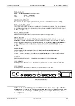
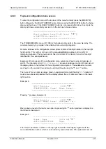
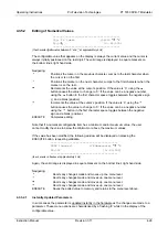
Reference input (ID 2600)
This menu allows the user to select the 10MHz clock reference source and to configure
parameters with respect to the 10MHz and 1PPS reference inputs. Sub menus are available for
selecting 10MHz source (menu ID 2610), impedance for the 1PPS reference input (menu ID
2620), impedance for the 10MHz reference input (menu ID 2630), and trigger level for the 1pps
input.
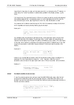
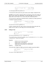
The 10MHz reference source can be set to Internal, External or Auto. By auto mode the unit will
synchronize to an external reference if available and automatically switch to the internal
reference if no external reference is available (no alarm will be raised if the unit switches to
internal reference). By external reference mode the unit will synchronize to an external 10MHz
when available and switch to the internal reference if no external reference is available (an
alarm will be raised if the unit in this mode needs to switch to internal reference due to absence
of external reference). Note: for SFN mode external reference should be selected.
4.3.4.5
ALARM Menu System (Menu ID 3000)
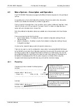
The alarm menu system (menu ID 3000) is accessed by pressing the [EXECUTE] button
followed by the [RIGHT ARROW] button as described in paragraph 4.3.4.1. When the menu
system is entered at menu TRANSMISSION use the [RIGHT ARROW] button to navigate to the
Alarm menu.
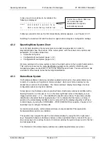
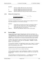
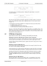
Define Alarm menu (ID 3100)
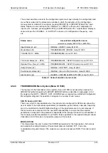
This menu allows the user to program the desired response for each of the possible alarms that
can be raised by the unit. For each type of alarm the user can choose to route the alarm to one
or several of the following destinations:
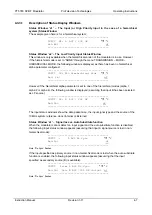
Alarm destination
Description
Mute
When the Mute option for an alarm is set to “ON” the alarm will
be routed to the mute control circuit. In this case the modulator
output will mute whenever the alarm is active.
Event Log
When the Event Log option for an alarm is set to “ON” the alarm
will be routed to the Event Log. In this case the time and date
when the alarm is raised and the time and date when the alarm
is lowered will be recorded in the event log together with the
specific name of the alarm type.
Relay 1
When the Relay 1 option for an alarm is set to “ON” the alarm
will be routed to Alarm 1 relay control circuit. In this case the
Alarm 1 relay contacts will be activated whenever the alarm is
active. The red ALARM led located in the front panel will be on
for the duration of the alarm.
Relay 2
When the Relay 2 option for an alarm is set to “ON” the alarm
will be routed to Alarm 2 relay control circuit. In this case the
Alarm 2 relay contacts will be activated whenever the alarm is
active. The red ALARM led located in the front panel will be on
for the duration of the alarm.
Содержание PT 5780
Страница 94: ......

