Operating Instructions
ProTelevision Technologies
PT 5780 DVB-T Modulator
Instruction Manual
Revision 3.11
4-16
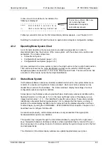
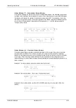
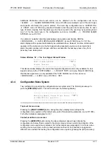
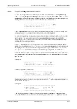
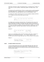
choice of standard channel rasters (ITU UHF combined with either the VHF B, VHF L or VHF I
raster) and a user defined channel raster. When the user-defined raster is selected the user can
configure this raster via sub menu 2231 with respect to base frequency and start channel
number. The ‘base frequency’ represents the centre frequency of the first channel in the user-
defined raster (for example 529,5 MHz). The ‘start channel number’ represents the number to
be assigned to the first channel in the user-defined raster (for example 28). The step size of the
channel raster will always follow the bandwidth of the modulator (for example 7MHz). These
three parameters values (529,5 MHz, ch no. 28, BW 7MHz) provides a channel raster that steps
as follows: CH28: 529,5MHz, CH29: 536,5MHz, CH30: 543,5MHz ……….(Australian UHF
System B)
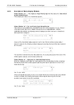
The
bandwidth
sub menu (ID 2240) allows the user to switch the bandwidth of the COFDM
spectrum between 8, 7 and 6MHz (6MHz bandwidth requires that option PT 8735 is installed).
The
Output Level
sub menu (ID 2250) allows the user to set the Output level
.
The adjustment
range for the IF version is +2/-8dB in steps of 0.1dB relative to nominal output level +6dBm. For
the RF version the adjustment rage is +0dB/-10dB relative to nominal output level (0dBm).
Note:
In case of the RF version (option PT 8715 installed) the IF output level is fixed to +6dBm
The
Window On/Off
sub menu (ID 2260) allows the user to switch on/off the “window” type
spectrum sideband filter function as required (as default the filter is switched on).
The
Window RollOff
sub menu (ID 2270) allows the user to adjust the trade-off between
obtained sideband suppression and cross talk between two successive COFDM symbols. The
default window ratio 1/64 provides maximum sideband suppression.
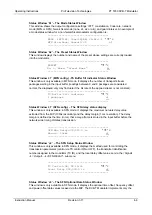
The
Spectrum
sub menu (ID 2280) allows the user to set the polarity of the spectrum as
required. When NORMAL polarity is selected carrier number 1 of the COFDM spectrum is
located at the lowest frequency whereas the last carrier number (1705 by 2K and 6817 by 8K) is
located at the highest frequency. When inverted polarity is selected carrier number 1 of the
COFDM spectrum is located at the highest frequency whereas the last carrier number (1705 by
2K and 6817 by 8K) is located at the lowest frequency. Note: for the RF version the selected
spectrum polarity refer to the RF output (the IF output will have the opposite polarity of the
polarity selected for the RF output).
The
SFN Delay
sub menu (ID 2290) allows the user to set a local delay offset relative to the
transmission timing specified via the MIP (the menu is only available in SFN mode). The
nominal adjustment range is +/- 999.999,9 ms in steps of 100ns. However, in practice the
applied value must respect the timing window set by the actual propagation delay from the
head-end to the modulator relative to the network delay specified in the MIP (maximum delay).
The transmission time cannot be advanced beyond the actual propagation delay from the head-
end to the modulator (the modulator must obviously receive the mega frame before it can
transmit it).
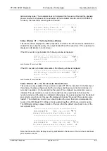
Non-Linear Pre -Correction (ID 2300)
This menu allows the user to control the non-linear pre-corrector function (only available when
option PT 8731 is installed). Sub menus are available for switching the pre-corrector function
on/off (menu ID 2310), for setting the gain of the pre-corrector (menu ID 2320), for setting the
peak clipping menu (ID 2330), and for recalling a correction curve from the preset library (menu
Содержание PT 5780
Страница 94: ......

