


1.2
1.1
IDENTIFICATION
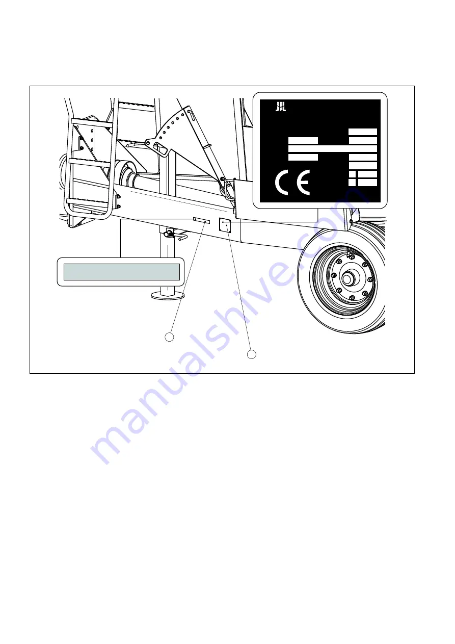
FIGURE 1.1A
LOCATION OF THE DATA PLATE AND FACTORY NUMBER
(1) data plate, (2) factory number
The feed car VMP-10 is equipped with data plate mounted on the left longitudinal member of
a bottom frame. Factory number is engraved on both the data plate and left longitudinal
member of a frame on rectangular field painted in silver. When purchasing the feed car it is
necessary to verify whether factory number engraved on the machine is same as written in
the WARRANTY CARD, sale documentation as well as in INSTRUCTIONS FOR USE AND
SERVICING.
Factory number of the carriageable axle as well as its type is punched on the data plate
attached to the beam of carriageable axle.
1
2
SZBVM10XX71X00001
Pronar Sp. z o.o.
ul. Mickiewicza 101A,17-210 Narew
tel./fax: (085) 681 63 29
e-mail: [email protected]
Rok prod.
Nr św. hom.
Nr fabr.
Symbol/Typ
Dop. obc. osi
Dop. m. całk.
Ładowność
Dop. obc. zacz.
Masa wł.
kN
kN
kg
kg
kN
kg
VMP10
SZBVM10XX71X00001
Содержание VMP-10
Страница 38: ...3 14 ...
Страница 52: ...4 14 ...
Страница 62: ...5 10 FIGURE 5 4A LUBRICATION POINTS OF THE FEED CAR 1 2 3 4 5 6 7 9 8 10 10 10 10 A B A B C C ...
Страница 75: ...5 23 THREAD STRENGTH RATING APPLIED FORCE Nm M8 8 8 20 M8 5 8 15 M6 5 8 5 ...
Страница 76: ...5 24 ...
Страница 77: ...NOTES ...
Страница 78: ... ...