


Pr
o
Minent
®
Page 31
Repairs
Change diaphragm
WARNING
•
Always take suitable precautions when using hazardous chemicals!
•
Ensure that the equipment is de-pressurised!
S
Empty the liquid end (turn the unit upside down and let the feed chemical run out, rinse with
a suitable material: rinse the liquid end thoroughly after use with hazardous materials!).
S
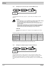
When gamma/ L is running set the stroke length to 0 % (the drive axis is then set).
S
Switch off the gamma/ L.
S
Unscrew the hydraulic connectors from the discharge and suction side.
S
For versions with coarse/fine bleed function: firstly pull out the coarse/fine bleed (knob),
then lift off the cover from the liquid end using a screwdriver.
S
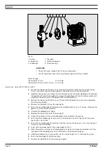
Remove the screws (1).
For pump types 0220, 0232 and 0420 see the following page (4 holes on the diaphragm rim)!
Standard types
S
Loosen the liquid end (2) and the top plate (4) from the pump housing (6) (loosen only!).
S
Hold the housing (6) in one hand and with the other, clamp the diaphragm (3) between the li-
quid end (2) and the top plate (4); release the diaphragm (3) from the drive spindle with a
light anticlockwise turn of the liquid end (2) and top plate (4).
S
Unscrew the diaphragm (3) completely from the drive spindle.
S
Remove the top plate (4) from the housing (6).
S
Check the condition of the safety diaphragm (5) and replace if necessary.
S
Push the safety diaphragm (5) only as far onto the drive axis until it lies flat on the pump
housing (6) – no further!
S
Screw the new diaphragm (3) carefully up to the stop on the drive axis – this must be exact
to ensure correct metering!
S
Screw the diaphragm (3) tight once more.
S
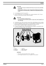
Position the top plate (4) on the pump housing (6).
TAKE CARE
•
The leakage hole must point downwards when the pump is fully assembled
(see fig. 23).
•
Position the top plate (4) correctly on the pump housing (6). Do not distort
the top plate on the pump housing , otherwise the safety diaphragm (5) will
not fit.
S
Lay the diaphragm (3) into the top plate (4).
S
Hold the top plate (4) and screw the diaphragm (3) in a clockwise direction until it is firmly in
position (you will feel the resistance of the return spring).
TAKE CARE
•
Do not overtighten the diaphragm (3) (particularly on type 1601).
•
The top plate (4) must remain in position to prevent the safety diaphragm (5)
from distorting.
S
Place the liquid end (2) with the screws (1) on the diaphragm (3) and the top plate (4) (the
priming connector must point downwards once the pump is fully assembled).
S
Screw on screws (1) lightly and tighten (starting torque, see below).
S
For versions with coarse/fine bleed function, ensure that the liquid end cover engages in the
liquid end, then push the coarse/fine bleed vent (knob) into the liquid end.