


Pr
o
Minent
®
Page 7
Assembly and Installation
PP, PC, NP, TT versions
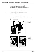
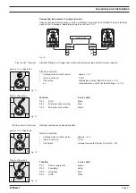
Assembling tubing to plastic valves
(see fig. 04)
S
Cut hose ends straight across
S
Push union nut (2) and clamping ring (3) onto hose (1)
S
Push the hose end (1) over the nozzle (4) to the stop. Widen if necessary
S
Make sure that the O-ring (5) is sitting correctly in the valve (6)
S
Place the hose (1) with the nozzle (4) onto the valve (6)
S
Clamp the hose connector:
Tighten the union nut (2) while pressing in the hose (1)
S
Retighten the hose connector:
Pull the tubing (1) connected to the liquid end briefly and then retighten the union nut (2)
1
2
4
5
6
3
1
Hose
1
2
4
5
3
1
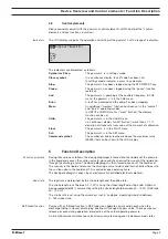
Tube
2
Union nut
2
Union nut ring
3
Clamping ring
3
Rear clamping
4
Nozzle
4
Front clamping ring
5
O-ring
5
Valve
6
Valve
Fig. 04
Fig. 05
SS Version
Assembling stainless steel tube connectors to stainless steel valves
(see fig. 05)
S
Push union nut (2) and clamping rings (3, 4) onto tube (1) leaving approx. 10 mm distance
between them
S
Push tube (1) up to the stop in the valve (5)
S
Tighten union nut (2)
SS Version
Assembling tubing to stainless steel valves
TAKE CARE
Assemble only
PE
or
PTFE
tubing to stainless steel valves!
S
Insert an additional support (stainless steel) into PE or PTFE tubing
Installing suction tubing
TAKE CARE
Do not exceed maximum permissible priming pressure on the prime side (see
section 14)!
GUIDELINE
•
Make suction tubing as short as possible.
•
Suction tubing should be rising in order to prevent air bubbles forming!
•
As far as possible use swept bends for bends rather than right angle bends!
•
Measure the length and cross section to ensure that the vacuum created by the
priming action does not reach the vaporising pressure of the feed chemical! In
extreme cases excess vacuum on the priming side can cause breaks in the liquid
column or incomplete return stroke!
•
Please note: “Priming lift x density of feed chemical
£
max. priming lift” (in m WG)
Assembly of foot valve
S
Cut the free suction end so that the foot valve hangs just above the container base; for
chemicals with impurities or sedimentation at the bottom, the foot valve should be
positioned well above this layer.