


Pr
o
Minent
®
Page 10
Assembly and Installation
gamma/ L configuration
Electrical interface for “external contact” - “pause” - “auxiliary frequency”:
•
Voltage when contacts open:
approx. 5 V
•
Input resistance:
10 k
W
•
Control:
voltage free contact (load: 0.5 mA at 5 V),
or:
Semiconductor switch (residual voltage < 0.7 V)
•
Maximum pulse frequency:
25 pulses/s
•
Required pulse duration:
³
20 ms
Electrical interface for “external analogue":
•
Input load resistance:
approx. 120
W
•
Maximum current at input:
50 mA
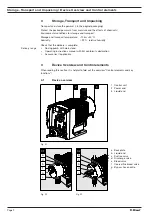
gamma/ L configuration
1
5
4
2
3
Pin
Function
2 core cable
4 core cable
5 core cable
Pin 1
Pause
Jumped at pin 4
Brown
Brown
Pin 2
External contact
Brown
White
White
Pin 3
External analogue
–
Blue
Blue
Pin 4
Earth
White
Black
Black
Pin 5
Auxiliary frequency –
–
Grey
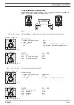
Fig. 08
Plug configuration
2
4
5
1
3
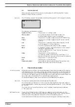
“Pause” function
The gamma/ L is not operating when
•
The cable is connected and pins 1 and 4 are free.
The gamma/ L is operating when
•
The cable is connected and pins 1 and 4 are connected.
•
There is no cable connected (pin 1 is free).
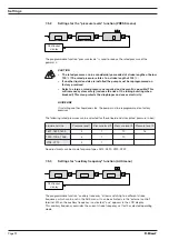
Fig. 09
“Contact” und “Batch” operating modes
One or more discharge strokes are triggered when pin 2 and pin 4 are connected to one another
for at least 20 ms.
Otherwise, pin 1 and pin 4 must be connected.
“Analogue” operating mode
The stroke frequency of the gamma/ L is controlled via an electrical signal. The electrical signal
is applied between pins 3 and 4.
Otherwise, pin 1 and pin 4 must be connected.
“Auxiliary frequency” function
The gamma/ L runs at a pre-set stroke rate when pin 5 and pin 4 are connected to one another.
Otherwise, pin 1 and pin 4 must be connected.
The factory setting for this function is 180 strokes.
GUIDELINE
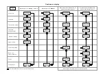
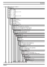
For function and operating mode hierarchy, see section 5!