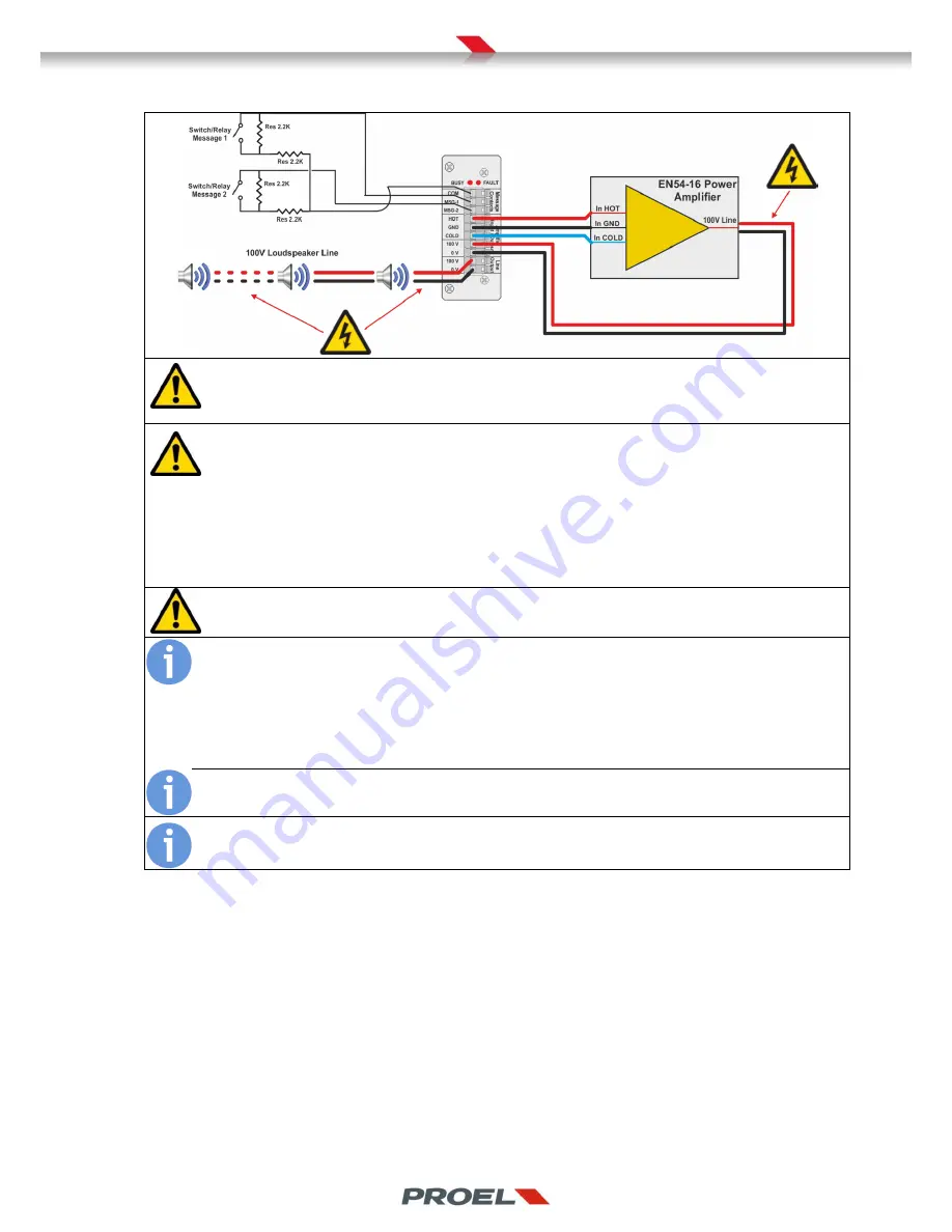
The system is compatible with power amplifiers having a floating 100V loudspeaker output; i.e. the output is not
referred to the input ground. The amplifier input shall be balanced (differential). The system can handle up to 500W
power.
The line module can monitor loads starting from approximately 30W. The term “approximately” is appropriated since,
during the calibration process, the module will first drive the power amplifier so that its output is 100V on the
loudspeakers line, then it will measure the load impedance and the nominal power absorbed by the load at 1KHz and
at 18KHz so that all other measurements will not be hearable by the residents in the building. At 18Khz the measured
impedance and power may be slightly different than at 1Khz since two fenomena occur: the gain attenuation of the amplifier and
the impedance of the loudspeakers will be surely higher than at 1Khz, according to the curve specified by the manfacturer.
Therefore, those cases where the matching of an amplifier with an extended frequency range to loudspeakers with a flat
impedance module, will allow the module to measure accurately even less than 5W. On the other hand, if the power amplifier has
a norrower response on higher frequencies, and loudspeakers impedence module increase on the same frequencies, it will be
harder for the line module to perform a consistent measurement on lower loads.
When designing the system setup and loudspeaker line, the engineer shall select an amplifier with sufficient power to
drive the loudspeaker line. It is advisable to keep some safety margin so that the load applied to the amplifier is
about 85-90% of the maximum deliverable power.
One of the procedures that are discussed in this manual is about the calibration of the loudspeaker lines; such
calibration is performed ad access level 2 or 3. During this automatic procedure, the system will verify that the
amplifier is effectively able to drive the loudspeaker and that the amplifier is not overloaded. This particular feature
will allow, during the commissioning of the system, to check that the dimensioning and installation of the loudspeakers is
coherent with the installed power amplifier. The system itself will perform as a test instrument to validate the entire setup
without any impedance meter.
The calibration procedure is also used by the system to acquire the initial parameters that will be used as a reference for all
other line and amplifier measurements and checks.
The 2.2Kohm resistors on the triggers for the recorded line messages shall be placed close to the fire alarm equipment
in order to effectively monitor the cable against cuts and shorts.
If the setup of the system does not require any input to trigger the recorded messages, the contacts shall be left open.


