background image

10–6

Chapter 10 – Control Panel


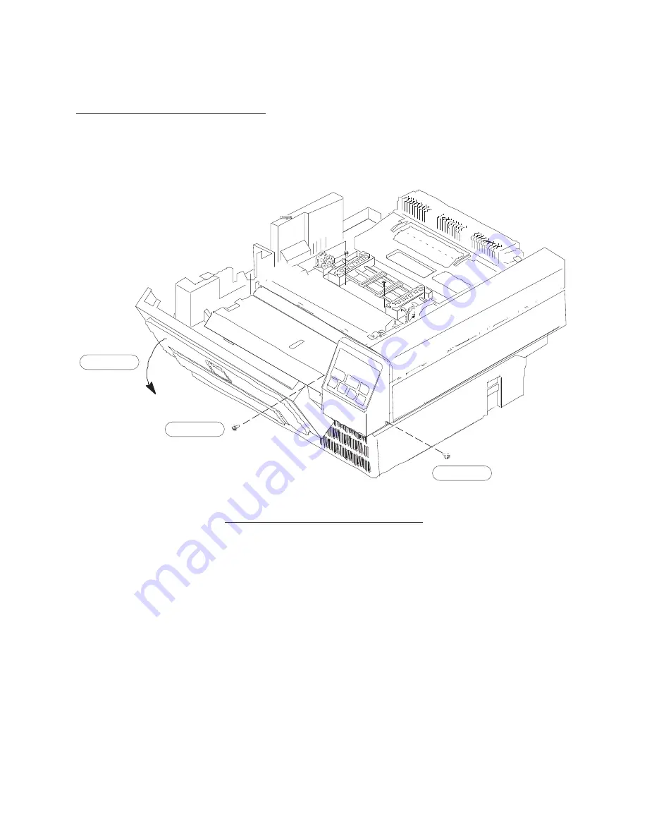
10.3.1 Removal and Disassembly

1.

Open the printer clamshell.

2.

Open the front cover. 

See Figure 10–1.

Step 4

Step 3

Step 2

Figure 10–1.  LCD Control Panel Removal

3.

Remove the screw on left front of the control panel.

4.

Remove the screw on the bottom right side of the control panel.

5.

Lift the control panel upward and to the right to disengage the tab and shaft.

CAUTION:

Be careful not to damage the cable.

6.

Disconnect the cable and remove the LCD panel.

NOTE:

Do not remove the board from the control panel as the LCD is aligned to
panel mask and buttons. The 

entire assembly should be replaced if any

problems occur with any of the components.

Содержание L1024

Страница 1: ...R...

Страница 2: ......

Страница 3: ...R P N 704792 001 Rev C...

Страница 4: ...e shielded for the printer to comply with FCC rules and regulations Part 15 governing the radiation limits for Class A equipment This digital apparatus does not exceed the Class A limits for radio noi...

Страница 5: ...view 2 8 Mechanical 2 8 Electrical 2 9 Top Cover Assembly 2 10 Removal and Disassembly 2 10 Reassembly and Replacement 2 13 Adjustment 2 13 Troubleshooting 2 13 Latch Assembly 2 14 Removal and Disasse...

Страница 6: ...5 8 Reassembly and Replacement 5 13 Adjustment 5 13 Troubleshooting 5 13 Engagement Lever 5 14 Removal and Disassembly 5 14 Reassembly and Replacement 5 18 Adjustment 5 18 Troubleshooting 5 18 Chapte...

Страница 7: ...30 Troubleshooting 7 31 Chapter 8 Power Supplies Power Supplies Parts Lists 8 2 Low Voltage Power Supply 8 2 High Voltage Power Supply 8 4 Overview 8 6 Low Voltage Power Supply 8 8 Removal and Disass...

Страница 8: ...hanical 10 3 Electrical 10 3 Control Panel 10 6 Removal and Disassembly 10 6 Reassembly and Replacement 10 7 Adjustment 10 7 Troubleshooting 10 7 Chapter 11 Laser Scanning Unit LSU Subystem LSU Parts...

Страница 9: ...shooting Guide 13 6 Guide to Error Mesages 13 26 Operator correctable Error Messages 13 26 Service Call Error Messages 13 27 Detailed Troubleshooting Guide 13 29 01 CLOSE THE COVER 13 29 02 LOAD PAPER...

Страница 10: ...Identification C 2 Disassembly Reassembly C 16 The Basic Frame C 16 The Tabletop C 17 The Paddle Drive Motor Assembly C 19 The Upper Drive Motor Assembly C 21 The Paddle Drive Belts C 22 The Paper She...

Страница 11: ...mes you are viewing the front of the printer For instance the control panel is on the RIGHT side of the front of the printer Notes and Notices that you need to pay special attention to are presented i...

Страница 12: ...E HIGH VOLTAGE SUPPLY TRACTOR LOW VOLTAGE SUPPLY MAIN DRIVE RIGHT FRAME LEFT FRAME DEVELOPER TENSION ROLLER LSU LASER SCANNING UNIT BOTTOM COVER LED ARRAY STEPPER MOTOR CONTROL BOARD HOUSING MOTOR OPC...

Страница 13: ...lled to service the printer check these items to be sure that the owner is replacing them according to the schedule below This user maintenance schedule provides the owner with the best quality printi...

Страница 14: ...the Waste Toner Container S Replace the Fuser Felt Wiper S Clean the Fuser Heat Roller S Clean the Transfer Corona Wire S Clean the Charge Corona Wire When Replacing the OPC Drum Unit approximately e...

Страница 15: ...n other parts as needed inside the printer including vacuuming the interior of the printer WARNING Turn off power to the printer before cleaning it NOTE The inside of the printer should be cleaned and...

Страница 16: ...especially if using regular paper after using labels Wet Wipe Tissue Turn off the printer Open the top and front covers of the printer Remove the OPC Drum Unit and the Developer Unit refer to the Set...

Страница 17: ...und the mylar sheet wipe the mylar first then use the brush for the wire S Around the Tractor S Inside the right cover S High Voltage Power Supply cover S Fuser paper guide S Transfer paper guide S Pa...

Страница 18: ...1 8 Chapter 1 Introduction...

Страница 19: ...2 1 Chapter 2 Clamshell Chapter 2 Clamshell Clamshell and Subassemblies...

Страница 20: ...ower Latch 11 Lever Release 12 Button Release 13 Shaft Latch 2 14 Button Locking 15 Shaft Locking 16 Frame Latch 17 E Ring 3mm I D Zinc 2 071151 004 18 E Ring 4mm I D Zinc 2 071051 006 19 Spring Torsi...

Страница 21: ...1 25 1 23 1 22 1 3 1 6 1 5 1 4 1 8 2 7 1 2 Ref 9 1 20 2 1 Ref 20 8 32 1 20 2 21 Ref 34 1 33 1 17 2 16 1 18 2 12 1 10 1 11 1 13 2 14 1 19 1 15 1 28 1 29 1 30 4 26 Ref 27 1 Latch Assembly Detail LED Ar...

Страница 22: ...mshell Catch Left 9 Shaft Clamshell Catch 200523 001 10 E Ring 5mm I D Zinc 071151 008 11 Screw PPH CLFW 3x8mm Zinc 2 030130 308 12 Catch Assembly Right 200871 001 702829 001 13 Clamshell Catch Right...

Страница 23: ...inge Assembly Left Hinge Assembly Left Catch Assembly Catch Release Assembly 2 Ref 17 1 18 1 15 1 19 2 14 2 16 1 8 1 11 2 7 Ref 9 1 10 1 1 Ref 4 1 2 1 5 1 3 1 12 Ref 9 1 10 1 Right Catch Assembly 6 2...

Страница 24: ...200605 001 4 Bracket Hinge 5 Shaft Hinge 6 Spring Compression Hinge 200607 001 7 Hinge Slide 200609 001 8 Retention Plate 200610 001 9 Frame Clamshell Hinge 200611 001 10 CE Ring 7mm I D Zinc 072151...

Страница 25: ...r 2 Clamshell NOTE This is the left side hinge The right side hinge is a mirror image of the left side hinge 11 1 2 Ref 3 Ref 4 1 5 1 6 1 7 1 10 1 9 1 8 1 14 1 16 1 17 1 1 1 15 1 12 1 13 1 11 2 Hinge...

Страница 26: ...the shafts on the Clamshell Catches S Left and Right Catch Assemblies The Catch Assemblies hold the Clamshell closed using the Clamshell Latch The Right Catch Assembly also acts as the Cover Open Inte...

Страница 27: ...Board to the LSU that passes through the Right Hinge Assembly The cabling block diagram for the Clamshell is shown below See Appendix B for a complete electrical block diagram J4 TO LSU 1 5 11 Backpl...

Страница 28: ...Removal and Disassembly 1 Open the Clamshell and remove 3 Screws from the Clamshell Frame see Figure 2 1 then lift the front of the Top Cover first to help disengage the LSU Locking Tabs from the rea...

Страница 29: ...2 11 Chapter 2 Clamshell Latch Removal Detail Top Cover Clamshell Frame Step 1 Step 3 Step 4 Step 5 Figure 2 1 Top Cover Disassembly...

Страница 30: ...2 12 Chapter 2 Clamshell 1 Lift Front Cover then disengage rear Locking Tabs 2 Depress tab to remove Hinge Cover Detail 2 1 Removing Top Cover and Hinge Covers...

Страница 31: ...Figure 2 1 4 Remove 2 screws then remove the Latch Assembly from the Top Cover See Figure 2 1 5 Remove the Toner Seals from the Top Cover only if absolutely necessary See Figure 2 1 2 3 2 Reassembly...

Страница 32: ...atch Spring from the Release Button See Figure 2 2 Step 2 Step 3 Step 4 Figure 2 2 Latch Assembly Disassembly 3 Remove the other E ring then slide the Latch Shaft free of the Latch Frame This frees th...

Страница 33: ...installing the Latch Assembly onto the Top Cover make sure the Latch Assembly is properly oriented with the Release Lever See Detail 2 2 CORRECT LATCH RELEASE POSITION Detail 2 2 Correct Latch Release...

Страница 34: ...3 Screws from the Clamshell Frame then lift the front of the Cover This helps disengage the Locking Tabs of the LSU from the rear of the Cover See Figure 2 1 and Detail 2 1 2 Remove 4 attachment scre...

Страница 35: ...Clamshell Left Catch Right Catch Catch Release Assembly Step 2 page 2 19 Step 4 page 2 19 Step 2 page 2 19 Step 3 page 2 19 Step 5 page 2 19 Step 2 Step 3 Step 2 page 2 19 Figure 2 3 Catch Release As...

Страница 36: ...e 2 5 2 Reassembly and Replacement Reverse Steps 1 through 3 listed above NOTE When reinstalling the Top Cover onto the Clamshell make sure the Latch Assembly is properly oriented with the Release Lev...

Страница 37: ...so that the Catches can be removed from the Clamshell Frames See Figure 2 3 3 Remove 2 screws then remove the Right Clamshell Catch 4 Remove 2 crews then remove the Left Clamshell Catch 5 Remove 1 E...

Страница 38: ...ver then gently lower this side See Detail 2 3 Slide the Bottom Cover slightly to the right to release the locking tabs on the left side then lower the Bottom Cover away from the printer and over the...

Страница 39: ...his is the left side hinge The right side hinge is a mirror image of the left side hinge Step 2 Step 2 Step 3 Step 4 Step 5 Step 6 Figure 2 4 Clamshell Hinge Removal DISASSEMBLY See Figure 2 4 3 Remov...

Страница 40: ...rse Steps 1 through 6 above 2 7 3 Adjustment Adjust the spring tension on the side of the hinge so that when the Clamshell is opened fully and released the Clamshell falls to a 30 angle and then stops...

Страница 41: ...and allows the toner image to be transferred to the page prior to fusing See Figure 3 1 This unit is factory assembled and factory adjusted No field adjustments are required Figure 3 1 OPC Drum Unit...

Страница 42: ...irst place the unit in the printer Then ensure that the unit is fully seated so that its contacts on the right side are properly set and so that the Waste Toner Auger Seal opens and fits properly over...

Страница 43: ...tory assembled and factory adjusted No field adjustments are required Figure 4 1 Developer Unit To remove the Developer Unit from the printer first open the top and front covers of the printer Then un...

Страница 44: ...4 2 Chapter 4 Developer Subsystem No disassembly is required 1 2 3 3 4 Figure 4 2 Removing the Developer Unit...

Страница 45: ...the plastic rails on each side until the unit is fully seated in the printer Lock both of the locking tabs If the Developer Unit that you are installing is a new one follow the instructions in the Ope...

Страница 46: ...4 4 Chapter 4 Developer Subsystem...

Страница 47: ...5 1 Chapter 5 Transfer Subsystem Chapter 5 Transfer Subsystem Transfer Charger...

Страница 48: ...a Assembly 202143 501 9 Screw PPH CLFW Zinc 3x8mm 2 030130 308 10 Paper Guide Plastic Rear 202148 001 11 Brush Static Discharge 202147 551 12 Screw PPH IW Chrome 3x6mm 2 030231 306 13 Shaft Transfer C...

Страница 49: ...5 3 Chapter 5 Transfer Subsystem 4 Ref 9 2 1 Ref 17 1 8 1 14 2 12 2 5 1 7 2 11 1 16 1 6 1 13 1 3 Ref 10 1 15 2 2 1 18 4 18 2 19 1 Transfer Charger Assembly...

Страница 50: ...fer Corona Assembly 202143 501 704539 064 2 Wire Transfer Corona 202144 001 3 Cover Transfer Corona 2 202145 001 4 Spring Extension Transfer Corona 200617 001 5 Housing Transfer Corona 200618 001 6 My...

Страница 51: ...200502 501 702701 001 2 Guide Engagement Lever 2 200500 001 3 Engagement Lever Unit 200499 551 4 Pulley Cam Lever 5 Shaft Pulley Cam Lever 6 Lever Engagement 7 Spring Extension Engagement Lever 200501...

Страница 52: ...e printing process It contains the Transfer Corona Static Brush and Paper Guide and is driven by the Engagement Lever Static Brush This brush removes the static charge that is built up during the tran...

Страница 53: ...ical Components Transfer Corona The transfer corona is a small 60 m wire that is charged to 4 600 volts 100 volts DC The input for the Transfer Corona Block Diagram 5 1 is connector pin CN 3 from the...

Страница 54: ...OPC and Developer Units and any paper that may be present in the Printer 2 Remove the Front Plastic Paper Guide from the Transfer Charger by pressing down on the center and ends then sliding it to the...

Страница 55: ...5 9 Chapter 5 Transfer Subsystem Step 5 Step 6 Step 7 Step 8 Step 4 Step 2 Step 3 Step 4 Figure 5 3 Transfer Charger...

Страница 56: ...ing it toward the rear of the Printer This makes it easier to disengage the Swing Shaft from the Engagement Lever See Detail 5 1 NOTE The Transfer Corona Assembly can be removed from the Transfer Char...

Страница 57: ...3 Corona Neck Is Placed Under Retaining Tab Detail 5 2 and 5 3 Removing the Static Brush and Rear Paper Guide Corona Contact and Locking Tab 6 Transfer Corona Assembly a Remove 2 Screws and lift the...

Страница 58: ...ragile and can be easily broken c To remove the Corona Wire gently pull on the small Eyelet at the opposite end of the Wire from the Spring and remove the small Eyelet from its Post CAUTION The Wire i...

Страница 59: ...r Subsystem 5 5 2 Reassembly and Replacement Reverse Steps 1 through 8 above 5 5 3 Adjustment No adjustment of the Transfer Charger Assembly is necessary 5 5 4 Troubleshooting See Chapter 13 for troub...

Страница 60: ...5 14 Chapter 5 Transfer Subsystem 5 6 1 Removal and Disassembly 1 Open the Clamshell remove the OPC Developer Unit and any paper present in the Printer See Figure 5 5...

Страница 61: ...Transfer Subsystem Step 5 Step 6 Step 7 Step 8 Step 9 Step 10 Step 11 Cover overlaps tractor assembly side frame Cover overlaps tractor assembly side frame Detail 5 6 Detail 5 5 Figure 5 5 Engagement...

Страница 62: ...Paper Guide to clear the Tabs of the Slots and release the Front Tabs by rotating the Paper Guide toward the front of the Printer 4 Remove 4 Screws from the bottom of the Transfer Charger Remove the...

Страница 63: ...5 17 Chapter 5 Transfer Subsystem Detail 5 4 Removing the Lamp Connector...

Страница 64: ...e from the Connector on the Base Plate behind the Tractor 11 Remove the Tractor by removing 3 Screws then lifting the left end of the Tractor out first This allows the the Encoder to clear the High Vo...

Страница 65: ...6 1 Chapter 6 Paper Feed Subsystem Chapter 6 Paper Feed Subsystem Paper Feed Subsystem...

Страница 66: ...Printronix Part No 1 Paper Guide Lower 202149 001 704539 068 2 Sensor Paper Empty 202278 551 704539 053 3 Wire Clamp Paper Empty Sensor 202288 001 4 Screw PPH CLFW 3x6mm 3 030130 306 5 Guide Paper En...

Страница 67: ...0567 001 6 Gear Transfer Tension Roller 202103 001 7 Bushing Tension Roller Long 201289 002 8 Bushing Tension Roller Short 201290 001 9 Shaft Assembly Tension Roller 202106 551 10 Shaft Tension Roller...

Страница 68: ...6 4 Chapter 6 Paper Feed Subsystem 2 1 3 1 4 1 5 1 6 1 7 1 8 1 10 1 11 2 12 1 13 2 14 1 15 1 16 1 17 1 18 1 5 1 18 1 15 1 13 2 16 2 9 Ref 1 Ref 19 Ref Tension Roller Assembly...

Страница 69: ...ssembly Developer Drive 16 Ball Bearing Gear Shaft 2 200683 551 17 Gear Drive Developer 200688 001 18 Gear Drive Tension Roller 200691 001 19 Shaft Assembly Front Main Drive 12 E ring 4mm I D Chrome 0...

Страница 70: ...Drive Gear Assembly continued Callout Name Vendor Part No Printronix Part No 35 Screw TPH MT 3x6mm Zinc 035128 306 36 Screw PPH CLFW 4x16mm Zinc 4 030130 416 38 Screw PPH CLFW 3x6mm Zinc 3 030130 306...

Страница 71: ...5 Ref 19 Ref 2 Ref 8 Ref 11 2 32 1 26 1 28 1 11 1 23 1 24 1 27 1 23 1 12 3 12 1 30 1 31 1 20 1 21 1 22 1 35 1 39 1 12 1 4 1 7 1 34 1 32 1 33 1 12 1 40 1 37 1 11 1 36 4 34 1 9 1 10 1 38 3 3 1 5 1 13 1...

Страница 72: ...202383 551 14 Centering Arm Right 200451 001 15 Stepper Motor Assembly Tractor 202742 501 16 Stepper Motor Tractor 202155 551 17 Bracket Mounting Tractor Motor 202156 001 18 Screw PPH CLFW 3x6mm Zinc...

Страница 73: ...ef 14 1 10 1 29 1 31 1 11 2 30 1 19 1 20 2 27 2 23 1 33 1 15 Ref 29 2 21 1 22 1 2 Ref 16 1 17 1 18 2 28 2 32 3 5 1 7 1 28 1 3 1 6 1 26 1 24 1 28 1 20 2 29 2 4 1 Front of Printer Right Side of Printer...

Страница 74: ...S Tractor Encoder The Tractor Encoder Board has two optical sensors that sense the 1 8 inch and 1 16 inch slots in the Encoder Wheels These pulses are sent to the Engine Controller Board and are used...

Страница 75: ...5VL 24VB PDWN3 PDWN1 1 24 10 15 20 5 CN2 CN6 1 2 CN5 1 6 J2 J3 J4 J5 J1 PRFAN1 PRFAN2 JAM SENSOR EXIT JAM SENSOR FUSER STEPPER MOTOR M3 PR CLUTCH 1 J5 CN3 CN7 CN4 1 6 J13 J2 J1 TRACTOR STEPPER MOTOR...

Страница 76: ...to the left This disengages the Locking Tabs and the Paper Guide can then be easily removed See Detail 6 1 Detail 6 1 Removing the Front Plastic Paper Guide 3 Remove 2 Screws at the rear of the Lower...

Страница 77: ...6 13 Chapter 6 Paper Feed Subsystem Cover overlaps tractor assembly side frame Detail 6 2 Step 4 Step 4 Step 3 6 4 1 Step 6 6 4 1 Step 5 6 4 1 Step 4 Figure 6 1 Removing the Lower Paper Guide...

Страница 78: ...from the left end of the Tension Roller Shaft then remove the Short Shaft Bushing 8 Slide the Shaft to the right remove the Spring Pin from the right end of the shaft then remove the Tension Roller G...

Страница 79: ...gently bend the spring to correct the dimensions B Shaft A B 0 492 0 01 inch 12 5 0 3 mm A Detail 6 3 Checking Tension Roller Shaft Positioning 12 The Teflon Pressure Roller Retaining Spring can be re...

Страница 80: ...using the locating pins Install the left end of the Paper Guide first then lock the tabs at the front into the slots on the Roller Frame Ensure that the Tabs do not ride too low under the Tension Rol...

Страница 81: ...Clamshell remove the OPC and Developer Units and any paper present in the Printer 2 Remove the Lamp Connector Cover by removing 1 Screw and sliding the cover toward the fuser Disconnect the Fuser Lamp...

Страница 82: ...6 18 Chapter 6 Paper Feed Subsystem Step 3 Step 2 Detail 6 5 Removing Connectors...

Страница 83: ...et by removing 2 Screws See Figure 6 3 NOTE The Cable Grounding Screw does not need to be removed 8 Loosen but do not remove 2 Screws on the top of the Stepper Motor Board Frame Remove the Frame Cover...

Страница 84: ...6 20 Chapter 6 Paper Feed Subsystem Step 7 Step 8 Step 9 Step 10 Step 10 Figure 6 3 Removing the Display Mounting Bracket...

Страница 85: ...talling the Stepper Motor onto the Frame the Cable Connector must face toward the rear of the printer Step 2 Step 4 Step 3 Step 5 Step 10 Step 1 Step 6 Step 7 Step 8 Step 9 Step 4 Figure 6 4 Stepper M...

Страница 86: ...Spring Pin of the Upper Gear Shaft with the Slot in the Frame and slide the Shaft to the left out of the Frame NOTE Remove the Spring Pin from the Shaft only if the Spring Pin or the left Bushing nee...

Страница 87: ...Motor loses coordination with the OPC Drum Unit and the Developer Unit even though the OPC Drum Unit and Developer Unit are new a Check the Stepper Motor wire harness b If the total page count is arou...

Страница 88: ...er 6 Paper Feed Subsystem Step 1 Step 2 Step 3 Step 4 Step 5 Step 6 Step 7 Cover overlaps tractor assembly side frame Cover overlaps tractor assembly side frame Detail 6 7 Detail 6 6 Figure 6 5 Tracto...

Страница 89: ...addle the top edge of the left end of the Tractor Frame See Detail 6 7 in Figure 6 5 5 Remove the Tractor Paper Guide by removing 1 Screw from the center rear of the Tractor Frame 6 Disconnect the Tra...

Страница 90: ...eed Subsystem Rear of Printer Step 5 Step 1 Step 3A Step 4 Step 6 Step 7 Step 9 Step 11 Step 3B Step 3C Step 9 Step 8 Right Side of Printer Front of Printer Left Side of Printer Step 8 Step 2 Figure 6...

Страница 91: ...on to the Encoder Wheel This adjustment affects the position of the first line of print in relation to the page perforation See Detail 6 8 Front of Printer Rear of Printer Left Side of Printer Detail...

Страница 92: ...ing marks on both tractors to the timing dot on encoder wheel Flat face of drive shaft faces the rear of the printer Rear of Printer Right Side of Printer Left Side of Printer Detail 6 9 Tractor Encod...

Страница 93: ...m the Tractor Assemblies NOTE Upon assembly the Drive Shaft must be installed so that the Timing Mark of each Tractor is facing up This aligns both Tractors so that the Paper Pins are in the center of...

Страница 94: ...nt is to be moved closer to the page break slide the Tractor Encoder Board toward the front of the printer b If the print is to be moved farther from the page break slide the Board toward the rear of...

Страница 95: ...Frame and the Contacts for the HVPS Disengage the Locking Tabs at the front of the Guide from the Tension Roller Frame 4 The Paper Empty Sensor can be removed from the Base Plate by releasing its ret...

Страница 96: ...nect the Paper Empty Sensor Cable from Connector S11 on the Backplane Board The Cable can now be routed through the Left Side Frame 6 6 2 Reassembly and Replacement Reverse the 6 Steps above 6 6 3 Adj...

Страница 97: ...7 1 Chapter 7 Fuser Subsystem Chapter 7 Fuser Subsystem Fuser Subsystem...

Страница 98: ...Frame Assembly Heat Roller 202190 551 17 Frame Heat Roller 18 Shaft Fuser Locating 4 19 Shaft Pivot Lower Assembly 2 20 Roller Assembly Heat 202194 501 21 Roller Fuser Heat 202195 001 22 Collar Heat R...

Страница 99: ...7 Fuser Subsystem 7 1 1 Fuser Assembly continued Callout Name Vendor Part No Printronix Part No 40 Caution Label 115V 202384 001 Caution Label 230V 202385 001 41 Fuser Wiper Not part of this assembly...

Страница 100: ...18 4 22 2 32 2 19 2 14 2 13 1 100 to 120V and 220 to 240V in common 220 to 240V or 100 to 120V 29 Ref 20 Ref 36 Ref 16 Ref 5 Ref 7 Ref 10 Ref 17 1 35 1 2 Ref 15 Ref 1 Ref 3 1 28 1 41 1 38 1 37 1 21 1...

Страница 101: ...Callout Name Vendor Part No Printronix Part No 42 Heat Shield Assembly Fuser 43 Heat Shield Fuser 202211 001 44 Caution Label High Temp 202386 001 45 Caution Label Fuser Felt 202387 002 46 Seal Dust 2...

Страница 102: ...02238 551 24 Frame Fuser Stepper Motor 202239 001 25 Fuser Clutch 202240 551 26 Wire Harness Fuser Clutch 202241 551 27 Gear Transfer Stepper Motor 202242 001 28 Gear Drive Heat Roller 202243 001 29 G...

Страница 103: ...1 20 1 19 1 26 1 24 1 23 1 12 2 74 1 71 4 7 2 5 2 74 1 6 2 46 2 52 1 53 5 48 1 80 2 4 2 44 2 50 1 51 1 49 1 69 1 69 1 52 1 52 1 52 1 52 3 22 2 21 2 77 1 78 1 71 1 75 1 76 1 71 2 72 2 74 1 47 Ref 2 Ref...

Страница 104: ...ion Exit Cover 2 202259 001 54 Lever Assembly Pressure Cam Left 202266 501 44 E Ring 4mm I D Zinc 071151 006 55 Lever Assembly Pressure Left 202267 551 56 Lever Pressure Left 57 Bushing Pressure Lever...

Страница 105: ...7 1 37 1 38 1 44 1 41 1 40 Ref 42 2 43 1 44 1 33 1 34 1 44 1 63 1 56 1 73 1 58 1 54 Ref 55 Ref 73 2 63 1 68 1 57 1 70 1 70 1 57 1 18 1 65 Ref 66 Ref 67 1 60 1 60 1 62 1 62 1 64 1 64 1 44 1 44 1 59 1 5...

Страница 106: ...d in conjunction with the pressure roller comes in contact with the paper The heat causes the toner to be fused onto the paper Fuser Roller Cam Shaft This shaft has a cam on it that causes the Pressur...

Страница 107: ...h is especially useful during narrow forms printing Fuser Cam Clutch This is a clutch that causes the Fuser Roller Cam Shaft to rotate in order to open or close the Fuser and move the Paper Handling L...

Страница 108: ...8 BGND BGND BGND 24 24 24 GND 5 2 202234 D162 202234 D162 202241 S212 202238 D112 202298 S208 202200 S802 202296 S210 1 10 202292 S211 LVPS TMRPW TMRSG CN4 J5 5 PRPOS PRINIT SCPUP SCPDN PJAM EJAM PRFA...

Страница 109: ...power consumption When the Data Controller sends a print command to the Engine Controller the Engine Controller switches the Fuser from Standby Mode to Fusing Mode If the engine is idle for approxima...

Страница 110: ...hell and remove the OPC and Developer Units as well as any paper present in the Printer 2 Remove the Fuser Heat Shield then remove the Lamp Connector Cover by removing 1 Screw Disconnect the Fuser Lam...

Страница 111: ...ser roller assembly from fuser base Cover overlaps tractor assembly side frame Detail 7 3 7 4 1 Step 8 7 3 1 Step 4 7 4 1 Step 6 7 4 1 Step 9 7 4 1 Step 4 7 4 1 Step 10 7 4 1 Step 11 7 4 1 Step 12 7 3...

Страница 112: ...DISASSEMBLY 6 Open then remove the Fuser Wiper Cover by gently pressing in on its retaining tabs Remove the Fuser Wiper See Detail 7 1 7 Remove the Upper Heat Shield by removing 1 Screw then releasin...

Страница 113: ...7 17 Chapter 7 Fuser Subsystem Fuser Roller Cover locking tab locations Step 8 Step 6 Step 7 Step 8 Pivot is on inside of Frame Step 7 Detail 7 1 Removing the Upper Heat Shield...

Страница 114: ...ide of the Fuser Pressure Roller Frame See Figure 7 2 220 to 240V only OR 100 to 120V and 220 to 240V in common 100 to 120V only Step 10 Step 10 Step 9 Step 11 Step 12 Step 12 Step 13 Step 15 Step 16...

Страница 115: ...ings are seized 13 Remove the Thermistor by removing 1 Screw See Figure 7 2 14 Disconnect both Lamp Leads from the Thermal Breaker then the Thermal Breaker and Bracket can be removed from the Fuser Ro...

Страница 116: ...e that you do not touch the lamp as fingerprints will cause it to fail Clean it with a cloth and isopropyl alcohol before reinstalling it 18 Remove the Heat Roller from the Heat Roller Frame by liftin...

Страница 117: ...side is flush against the locating notches Put the Bracket Screw in place so that it holds the Bracket loosely in place 2 Hold the Fuser Roller up into the top of the Frame to simulate a closed Fuser...

Страница 118: ...rew from the center rear of the Tractor Frame 5 Open the Paper Exit Guide of the Fuser Base so that it is not in contact with the Fuser Roller Assembly 6 Depress the Fuser Assembly Retaining Lever on...

Страница 119: ...hapter 7 Fuser Subsystem Step 13 Step 13 Step 13A Step 13B Step 13B Step 13C Step 13D Step 13E Step 14 Step 16 Step 35 Step 32 Step 33 Step 31 Step 33 Step 34 Step 36 Figure 7 3 Paper Exit Cover Disas...

Страница 120: ...ep 15 Step 17 Step 19 Step 18 Step 20 Step 21 Step 22 Step 23 Step 24 Step 25 Step 25B Step 25C Step 25D Step 26 Step 22 Step 28 Step 27 Step 28 Step 29 Step 30 Step 31 Step 30 Step 26 Step 25A Step 2...

Страница 121: ...of the Shaft CAUTION The Locking Tabs of the Gear can be easily broken and must be gently pried free of the Shaft e Remove the Exit Guide Jam Lever from the Frame by gently spreading the Arms of the...

Страница 122: ...Remove 1 E ring then remove the Exit Guide Drive Gear 20 Remove 1 E ring from the Shaft for the Fuser Clutch then remove the Fuser Clutch from the Shaft NOTE Do not disassemble the Fuser Clutch Keep a...

Страница 123: ...ng Cam Dowel Pin from the Shaft c Remove the E ring for the Speed Control Cam and slide the Cam to the left and off of the Shaft Remove the Speed Control Cam Dowel Pin from the Cam Shaft d Remove the...

Страница 124: ...end of the Lift Remove the Rear Paper Lift from the Fuser Base Frame 27 Disconnect the Cable from the Fuser Jam Sensor then remove the Sensor by carefully releasing the retaining tabs from the Fuser B...

Страница 125: ...Assembly from the Fuser Base Frame NOTE Make sure to note the direction of the Return Spring 32 Remove 1 E ring and remove the Cam Follower and Shaft from the Left Cam Pressure Lever NOTE Make sure t...

Страница 126: ...a digital voltmeter for this measurement Under normal conditions the following voltages will be present across the Fuser Thermistor Fuser Temperature Approx Voltage Across Thermistor Approx 20 C ambie...

Страница 127: ...ng initial power up and during any warmup period there is a signal generated in the engine controller called HEAT This signal is generated by monitoring the TMRSG line returning from the thermistor Wh...

Страница 128: ...Chapter 7 Fuser Subsystem Thermal Breaker C D A A B B Lamp Thermistor 100 to 120V and 220 to 240V in common 100 to 120V or 220 to 240V S211 CNS1 Figure 7 5 Fuser Lamp Thermal Breaker and Thermistor De...

Страница 129: ...the cover interlock switch there is 115 VAC at various parts of the power supply and high voltage at other contacts so BE VERY CAREFUL Be sure that all cables and test leads are out of the way of any...

Страница 130: ...nd all consumable items from the printer Then remove the bottom cover from the printer per the cover removal section Check continuity between the Low Voltage Power Supply CN2 16 and the engine control...

Страница 131: ...meter surface reading probe Thermistor Malfunction Symptoms There are several conditions where you might suspect that the heat sensing control circuit is malfunctioning S If a THRMISTR FAIL or HEATER...

Страница 132: ...roller is not in its initial position and after it acts according to print requests If there is data to be printed the motor and the clutch are activated and the fuser is cantilevered against the pres...

Страница 133: ...8 1 Chapter 8 Power Supplies Chapter 8 Power Supplies High Voltage Power Supply Low Voltage Power Supply Power Supplies...

Страница 134: ...2 F1 and F2 200465 019 8 Fuse 125V 15A F3 201938 014 9 Screw PPH CLFW 3x10mm Zinc 030130 306 10 Cover Top LVPS 202577 001 11 Switch Power LVPS 202578 551 12 Screw PPH CSW 3x6mm Chrome 2 030235 306 13...

Страница 135: ...8 3 Chapter 8 Power Supplies 1 Ref 12 2 4 Ref CN5 CN6 CN4 F3 F2 F1 CN3 RV1 RV4 RV2 CN2 CN1 A To Fuser A CN2 CN1 5 1 6 1 9 1 2 1 10 1 3 1 11 1 9 1 8 1 7 2 Low Voltage Power Supply...

Страница 136: ...4 Chapter 8 Power Supplies 8 1 2 High Voltage Power Supply Callout Name Vendor Part No Printronix Part No 1 High Voltage Power Supply 202126 551 001 704539 033 2 Screw PPH CLFW M3x10 Zinc 2 030130 31...

Страница 137: ...8 5 Chapter 8 Power Supplies 1 1 2 2 High Voltage Power Supply...

Страница 138: ...2 VDC for operation of motors logic boards floppy disk drives and the control panel The HVPS provides 400 mA for the charge corona 720 VDC for the charge grid 4 600 VDC for the transfer corona and 550...

Страница 139: ...DB2 DB3 DB4 DB5 DB6 DB7 6 7 8 9 10 11 12 13 14 15 16 18 19 20 21 22 23 24 17 SWRST SWONL SWFF LDATA SWMENU LONLN SWSTOR LRDY SWDWN Vss Vdd J3 TO LCD CONTROL PANEL SWUP NOT USED Thermal Breaker Haloge...

Страница 140: ...Voltage Conversion and Fuse Replacement 1 Open the Clamshell remove the OPC Drum Unit Developer Unit Waste Toner Container and any paper present in the printer 2 Remove the Lamp Connector cover by rem...

Страница 141: ...emoving 1 Screw then pressing down on the Warning Label at the front of the Cover This releases the Locking Tab from the Right Side Cover See Figure 8 2 NOTE Upon installation the groove on the bottom...

Страница 142: ...the Connectors through the hole in the Printer Base Plate See Figure 8 1 5 Place the printer on a phone book or other similar item so that the Bottom Cover edges are not resting on the item Press gent...

Страница 143: ...8 11 Chapter 8 Power Supplies Bottom Cover Locking Tabs Figure 8 3 Bottom Cover Removal 6 Remove the printer from the phone book and disconnect 2 Cables from the front of the LVPS See Figure 8 4...

Страница 144: ...8 12 Chapter 8 Power Supplies Figure 8 4 Removing the LVPS Cables...

Страница 145: ...tion and slide the LVPS free of the Base Frame Feed the Lamp Power Wire Harness through the Printer Base Plate See Figure 8 5 CAUTION Use care to avoid damaging the Fuser Lamp Connector Ensure that it...

Страница 146: ...8 14 Chapter 8 Power Supplies 5 4 2 3 1 Figure 8 5 Removing the LVPS...

Страница 147: ...8 15 Chapter 8 Power Supplies Cable Routing Figure 8 6 LVPS Cable Routing...

Страница 148: ...8 16 Chapter 8 Power Supplies Figure 8 7 LVPS Locking Tabs 8 To remove the LVPS Cooling Fan disconnect the Cable from Connector CN3 remove 2 Screws then remove the Cooling Fan...

Страница 149: ...m Cover edges are not resting on the item Press gently to release the 2 Locking Tabs on the right side of the Bottom Cover then gently lower this side Slide the Bottom Cover slightly to the right to r...

Страница 150: ...8 18 Chapter 8 Power Supplies Figure 8 9 Removing the LVPS Cables...

Страница 151: ...Frame switch it to the ON position and slide the LVPS free of the Base Frame See Figure 8 10 CAUTION Use care to avoid damaging the Fuser Lamp Connector Ensure that it does not catch on the Base Plat...

Страница 152: ...8 20 Chapter 8 Power Supplies 5 4 2 3 1 Figure 8 10 Removing the LVPS...

Страница 153: ...8 21 Chapter 8 Power Supplies Cable Routing Figure 8 11 LVPS Cable Routing...

Страница 154: ...ower Wire Harness 5 To change the input voltage of the LVPS remove 1 Screw and remove the Connector Bracket Disconnect the Cable from Connector CN5 or CN6 and connect it to the free one CN5 is for 115...

Страница 155: ...8 23 Chapter 8 Power Supplies 115V Position 230V Position 1 2 3 1 2 3 Figure 8 13 Changing LVPS Input Voltage...

Страница 156: ...Connector or Fuse Function Destination CN1 Engine Controller Board Power 5V J7 on Backplane Board CN2 Stepper Motors Controller Board Power CN1 on Stepper Motors Controller Board CN2 Engine Controller...

Страница 157: ...s loosens the Mounting Bracket so it can be slid free of the Base Plate c Lift the front edge of the Cover to disengage the Locking Tabs then slide the Cover toward the rear of the printer to disengag...

Страница 158: ...8 26 Chapter 8 Power Supplies Step 3 Step 4 Step 6 Step 5 Step 7 Figure 8 15 Removing the Transfer Charger Paper Guides...

Страница 159: ...that the Brush Frame is in front of the Locking Tab for the Corona Assembly See Figure 8 16 Static Brush Is Placed In Front Of Retaining Tab Figure 8 16 Reinstalling the Static Brush 6 Remove 2 Screws...

Страница 160: ...8 28 Chapter 8 Power Supplies Step 8 Step 9 Step 10 Step 11 Step 12 Step 13 Step 14 Cover overlaps tractor assembly side frame Cover overlaps tractor assembly side frame Figure 8 17 Removing the Fuser...

Страница 161: ...on the bottom of the Encoder Cover should straddle the top of the left end of the Tractor Frame See detail in Figure 8 17 12 Remove the Tractor Paper Guide by removing 1 Screw from the center rear of...

Страница 162: ...ble from the rear of the HVPS and remove 1 Screw from the rear of the HVPS Slide the HVPS toward the rear of the printer to release the Front Locking Tab from the Base Plate See Figure 8 18 NOTE Upon...

Страница 163: ...ns connections and control interface for the HVPS Use these as a guide to adjusting the small controls on the side of the HVPS itself See Figure 8 19 NOTE The user adjustable developer bias knob on th...

Страница 164: ...32 Chapter 8 Power Supplies Adjustments CH2 CH3 CH1 CH6 CN2 CN6 CN1 CN3 User Adjustable Developer Bias Adjustment Contactor Assembly Lock down tabs Figure 8 19 High Voltage Test and Adjustment Points...

Страница 165: ...line of the LCD 8 Press the Down key Press Next until TEST PRINT appears on the bottom line of the LCD 9 Press Down Press Next until NO OF PAGES appears on the bottom line of the LCD 10 Press Down Pre...

Страница 166: ...Restore the following to their normal non disabled states S Paper empty switch S Cover interlock switch S Top of form switch S OPC drum switch 18 Install the OPC Drum Unit and the Developer Unit then...

Страница 167: ...rives Chapter 9 Controllers and Floppy Disk Drives BASE PAN HIGH VOLTAGE SUPPLY LEFT FRAME BOTTOM COVER STEPPER MOTOR CONTROL BOARD HOUSING ENGINE CONTROLLER BOARD CLAMSHELL BACKPLANE BOARD DATA CONTR...

Страница 168: ...9 2 Chapter 9 Controllers and Floppy Disk Drives Callout Name Vendor Part No Printronix Part No 1 Controller Assembly Data L1024 704598 001 Data Controller Board...

Страница 169: ...es Callout Name Vendor Part No Printronix Part No 1 Engine Controller Board L1024 202505 551 704539 108 2 Backplane Board L1024 202289 552 704539 107 1 Bottom Frame Backplane Board 2 Engine Controller...

Страница 170: ...51 704539 111 6 Actuator Cover Open 202172 001 704539 112 7 Actuator Drum Sensor 202173 002 704539 113 8 Label Inlet Hole Cover 202174 001 9 Screw PPH CLFW 3x6mm Zinc 8 030030 306 10 Screw PPH CLFW 3x...

Страница 171: ...9 5 Chapter 9 Controllers and Floppy Disk Drives Right side view Left side view 13 1 1 Ref 8 1 9 1 10 1 9 1 6 1 7 1 3 1 5 1 4 1 15 1 14 1 16 1 2 1 11 4 9 2 9 2 9 2 12 1 Stepper Motors Controller Board...

Страница 172: ...r Part No Printronix Part No 1 Disk Drive Assembly 3 5 Inch L1024 704627 001 2 Cable Kit L1024 704612 001 3 Disk Drive Floppy 3 5 Inch 2 MB 202377 001 4 Screw FL 90D M3x5 Phil STL ZN 5 Clamp Flat Cabl...

Страница 173: ...9 7 Chapter 9 Controllers and Floppy Disk Drives Drive A Standard Drive B Optional Floppy Disk Drives...

Страница 174: ...trol Panel S Floppy Disk Drives S Engine Controller Board S Host Computer The Engine Controller Board acts as interface between the Data Controller Board and the electromechanical portions of the prin...

Страница 175: ...that secure the Data Controller Board See Figure 9 1 CAUTION The Floppy Disk Drive Data and Power Cables must be disconnected from the Data Controller Board before the board can be removed from the pr...

Страница 176: ...lers and Floppy Disk Drives J10 J5 Screw 4 Figure 9 1 Removing Data Controller Board 9 6 2 Reassembly and Replacement Reverse Steps 1 through 5 above 9 6 3 Adjustment No adjustment of the Data Control...

Страница 177: ...ard interface to the host computer located on the Data Controller Board S The interface cables between the Data Controller Board and the host conputer S A configuration mismatch between the printer an...

Страница 178: ...izes LEDs L1 and L2 will indicate the various portions of the boot sequence as shown in Table 9 1 Table 9 1 Data Controller Board Boot Sequence L1 L2 Meaning Off Off Initial State On On Running DRAM D...

Страница 179: ...e Data Controller Board remains on Table 9 2 lists the beep and LED error codes Table 9 2 Data Controller Board Beep and Diagnostic LED Error Codes Diagnostic Status LED Flash Beep Pattern LCD Message...

Страница 180: ...unning faster than the printer engine speed During normal operating conditions LED L3 will be somewhere between the two extremes of continuously on and continuously off and will appear dimmed This con...

Страница 181: ...ors on the board See Figure 9 1 on page 9 10 4 Disconnect the Floppy Disk Drive data and power connectors from the Data Controller Board 5 Slide the Data Controller Board out the rest of the way and r...

Страница 182: ...secures the Engine Controller Board 8 Unplug the Engine Controller Board from the Backplane Board and remove the Engine Controller Board from the printer through the opening in the rear of the printer...

Страница 183: ...nit and any paper present in the printer 2 Remove the Lamp Connector Cover by removing 1 Screw and disconnect the Fuser Lamp and Thermistor Connectors from the Right Side Frame See Figure 9 5 and Figu...

Страница 184: ...Inside Cover should straddle the top edge of the right side of the Tractor Frame See Detail 9 1 in Figure 9 5 4 Open the Printer Front Cover and remove the LCD Control Panel by removing 2 Screws 5 Rem...

Страница 185: ...9 19 Chapter 9 Controllers and Floppy Disk Drives Detail 9 2 Step 7 Step 2 Figure 9 6 Releasing Heater Lamp and Thermistor Connectors...

Страница 186: ...isconnect 7 Cables from the Board These Cables are at connectors CN1 CN2 CN3 CN4 CN5 CN6 and CN8 See Figure 9 7 and Detail 9 3 in Figure 9 7 NOTE The 3 Stepper Motor Cables connect to Connectors CN3 C...

Страница 187: ...py Disk Drives Right side view Left side view Detail 9 3 Stepper Motors Controller Board Connectors Detail CN5 CN4 CN3 CN1 CN7 CN2 CN8 CN6 Step 8 Step 12 Step 11 Figure 9 7 Stepper Motors Controller B...

Страница 188: ...move the Tractor Paper Guide by removing 1 Screw then disconnect the Cable from the Fuser Remove 1 Screw from the Cable Tie to release the Cable from the Base Plate of the printer See Figure 9 8 11 Re...

Страница 189: ...and Floppy Disk Drives Depress white retaining levers to release fuser roller assembly from fuser base J 1 Connector Step e Step 9 Step 10 Step d Step b Step c Figure 9 8 Preparation for Removing the...

Страница 190: ...and remove it from the printer 12 Remove 2 Screws from the Stepper Motor Board Frame and remove the Frame See Figure 9 7 on page 9 21 DISASSEMBLY NOTE Except for the Ozone Fan all of the components l...

Страница 191: ...Stepper Motor CN4 Tractor Stepper Motor Tractor Stepper Motor CN5 Fuser Stepper Motor Fuser Stepper Motor CN6 Fuser Cam Motor and Clutch Fuser Cam Motor and Clutch CN7 Ozone Fan Upper Board Housing Fa...

Страница 192: ...connected from the Data Controller Board before the board can be removed from the printer 7 Slide the Data Controller Board out of the printer part of the way until you can gain access to the Floppy D...

Страница 193: ...9 27 Chapter 9 Controllers and Floppy Disk Drives Floppy Disk Drive Frame Floppy Disk Drive Frame Ref Floppy Disk Drive Guide Bezel Step 12 Step 5 Figure 9 10 Removing Drive Frame from Printer...

Страница 194: ...en you install a Floppy Disk Drive be sure to orient the Data Cable correctly when you connect it to the rear of the Drive 3 Remove 4 Screws from the bottom of each Floppy Disk Drive and remove the Dr...

Страница 195: ...9 29 Chapter 9 Controllers and Floppy Disk Drives Drive A Standard Drive B Optional Step 2 Step 3 Figure 9 11 Removing Drives from Drive Frame...

Страница 196: ...the Drive NOTE When you replace a Floppy Disk Drive be sure to correctly set the Drive Addressing Jumpers and or Switches on the new Drive before you install it The first or only Drive in the printer...

Страница 197: ...inter as described in section 9 6 1 2 Remove the screw holding the I O cover plate to the L1024 data controller pan 1 Save the screw 3 Screw the standoff 5 onto the pan through the hole next to C54 4...

Страница 198: ...9 32 Chapter 9 Controllers and Floppy Disk Drives 1 2 3 4 5 6 7 Figure 9 12 Expansion C T Board...

Страница 199: ...10 1 Chapter 10 Control Panel Chapter 10 Control Panel Keypad LCD Control Panel...

Страница 200: ...ol Panel Callout Name Vendor Part No Printronix Part No 1 Control Panel Assembly L1024 202117 552 704539 048 2 Screw PPH W CLFW M3x8 Zinc 2 030130 308 3 Overlay Sheet 202316 001 3 1 1 1 2 1 2 1 Connec...

Страница 201: ...nector CN on the back of the display panel This is connected to a straight through 26 pin connector and via a 26 wire cable to the engine controller at J3 This connector is keyed to make sure it can b...

Страница 202: ...rm Feed Key 18 SW Menu Menu Key 19 SW Store Store Key 20 SW Up Up Arrow Key 21 SW Down Down Arrow Key 22 LED Ready Ready LED 23 LED Online On Line LED 24 LED Data Data LED 25 LEDRSV1 Reserved LED outp...

Страница 203: ...ELOPER 24VB BGND CHARGE DEVELOPER TRANSFER J1 1 2 3 4 5 RSVD RS R W E DB0 DB1 DB2 DB3 DB4 DB5 DB6 DB7 6 7 8 9 10 11 12 13 14 15 16 18 19 20 21 22 23 24 17 SWRST SWONL SWFF LDATA SWMENU LONLN SWSTOR LR...

Страница 204: ...ol panel 4 Remove the screw on the bottom right side of the control panel 5 Lift the control panel upward and to the right to disengage the tab and shaft CAUTION Be careful not to damage the cable 6 D...

Страница 205: ...le See Figure 10 2 This cable plugs into the Backplane Board at J3 and connects to the display panel at connector CN There are seven keys membrane type switches on the panel that allow the user to pro...

Страница 206: ...ontroller 2 Keys not operating properly The seven keys on the panel have a decal attached to the plastic housing that makes up the bulk of the display panel The key coverings in turn press against sev...

Страница 207: ...11 1 Chapter 11 Laser Scanning Unit LSU Subsystem Chapter 11 Laser Scanning Unit LSU Subsystem Clamshell Frame LSU Assembly Top Cover LSU Subsystem...

Страница 208: ...Vendor Part No Printronix Part No 1 LSU Assembly L1024 202118 551 2 Housing LSU 202395 551 3 Top Cover LSU 202396 001 4 Label S N LSU 202397 001 5 Label Warning Laser 200892 001 6 Label Warning LSU S...

Страница 209: ...11 3 Chapter 11 Laser Scanning Unit LSU Subsystem Top View 2 1 1 1 3 1 4 1 5 1 6 1 7 1 8 3 LSU Assembly...

Страница 210: ...rt No 10 Erase LED Assembly 200542 551 702724 001 11 Cover LED Assembly 200541 001 12 Mount LED Plastic 200866 001 13 Board Assembly LED 200921 551 14 Screw PPH PTC 3x8mm Zinc 4 030129 308 15 Screw PP...

Страница 211: ...definition S LED Array Erase LEDs Generates light to remove the residual charge from the OPC drum S LSU Base Plate Supports and positions the LSU helps protect the LSU from the waste heat coming from...

Страница 212: ...J1 1 2 3 4 5 RSVD RS R W E DB0 DB1 DB2 DB3 DB4 DB5 DB6 DB7 6 7 8 9 10 11 12 13 14 15 16 18 19 20 21 22 23 24 17 SWRST SWONL SWFF LDATA SWMENU LONLN SWSTOR LRDY SWDWN Vss Vdd J3 TO LCD CONTROL PANEL S...

Страница 213: ...cking Tabs of the LSU from the rear of the Cover See Figure 11 1 and Detail 11 1 NOTE When reinstalling the unit the LSU must be properly located and seated in position by the locking pins in the LSU...

Страница 214: ...11 8 Chapter 11 Laser Scanning Unit LSU Subsystem Clamshell Frame Top Cover Step 1 Figure 11 1 Top Cover Disassembly...

Страница 215: ...11 9 Chapter 11 Laser Scanning Unit LSU Subsystem Detail 11 1 Removing the Top Cover...

Страница 216: ...ail 11 2 CAUTION The LSU is a sealed assembly Do not attempt to open the LSU or repair it Opening the LSU will cause it to become contaminated If there is a problem with the LSU replace it 11 3 2 Reas...

Страница 217: ...m Correct Latch Release Position Detail 11 3 Clamshell Latch Reassembly 11 3 3 Adjustment When reassembling the unit ensure that the Clamshell and its Latch are oriented properly 11 3 4 Troubleshootin...

Страница 218: ...disconnect the connector on the Erase LED Wire Harness and remove the Erase LED Harness Bushing Remove 2 Screws from the ends of the Erase LED Assembly Frame See Figure 11 2 CAUTION The Erase LED Wire...

Страница 219: ...11 13 Chapter 11 Laser Scanning Unit LSU Subsystem LED Connector Top Cover Bushing Figure 11 2 Erase LED Removal...

Страница 220: ...the entire LED Board and Mount together NOTE The Erase LEDs are soldered directly to the LED Board Thus if any LEDs are defective replace the entire LED Board 11 4 2 Reassembly and Replacement Revers...

Страница 221: ...12 1 Chapter 12 Covers Frame and Backplane Board Chapter 12 Covers Frame and Backplane Board Covers and Frame Components...

Страница 222: ...9 Screw PPH CLFW 3x6mm Zinc 3 030130 306 10 Cover Right Inside 202123 001 704539 121 11 Cover Lamp Connector 202124 001 704539 122 12 Cover Tractor Encoder 200471 001 13 Ozone Filter Case 200470 001...

Страница 223: ...12 3 Chapter 12 Covers Frame and Backplane Board 6 Ref 12 1 17 1 18 2 19 2 7 1 13 1 9 1 11 1 10 1 8 1 9 2 20 1 21 1 2 1 19 1 3 1 4 1 19 1 22 1 23 1 5 1 19 3 25 1 Covers...

Страница 224: ...Chapter 12 Covers Frame and Backplane Board Callout Name Vendor Part No Printronix Part No 14 Cover Hinge Left 202119 001 704539 116 15 Cover Hinge Right 202120 001 704539 117 21 Label Class 1 201394...

Страница 225: ...12 5 Chapter 12 Covers Frame and Backplane Board 14 1 15 1 21 1 Hinge Covers...

Страница 226: ...n Clamshell Latch 200514 001 702716 001 11 Lever Safety Left 200516 001 702718 001 12 Spring Torsion Safety Lever 200515 001 702717 001 13 Board Assembly Sensor Toner 202115 551 702711 001 14 Contact...

Страница 227: ...pter 12 Covers Frame and Backplane Board 2 Ref 1 Ref 21 1 20 1 4 1 8 1 9 1 22 1 6 1 10 1 11 1 17 1 17 1 12 1 22 1 3 1 5 1 7 1 14 2 18 1 22 1 23 1 13 1 15 1 16 1 19 1 High Voltage Warning Label Left Si...

Страница 228: ...Latch 200514 001 702716 001 10 Clamp Developer 200512 001 702714 001 11 Lever Safety Right 200621 001 702761 001 12 Spring Torsion Safety Lever 200515 001 702717 001 13 Spring Grounding OPC Drum 2006...

Страница 229: ...12 9 Chapter 12 Covers Frame and Backplane Board 14 2 12 1 15 1 11 1 17 1 7 1 16 1 10 1 3 1 4 1 6 1 17 2 13 1 5 1 17 1 17 1 15 1 8 1 9 1 2 Ref 1 Ref Right Side Frame...

Страница 230: ...286 001 704539 103 10 Guide Bezel Floppy Disk Drive 202287 002 704539 118 11 Backplane Board 202289 551 704539 107 12 Clamp Mounted Wire Harness 202290 001 13 Screw PPH 3x6mm Zinc 14 030130 306 19 Lab...

Страница 231: ...12 11 Chapter 12 Covers Frame and Backplane Board NOTE Arrows show attachment screw positions 19 1 1 Ref 14 1 17 1 13 1 18 1 15 1 16 1 12 1 4 1 7 1 6 1 2 1 9 1 10 1 11 1 8 2 5 1 3 4 21 3 Base Frame...

Страница 232: ...ers Frame and Backplane Board This section deals with parts not included in any other sections and includes S Covers Ozone Filter Case and Rating Labels S Left Side Frame S Right Side Frame S Base Fra...

Страница 233: ...of the printer See Figure 12 1 a Remove 2 Screws from the Left Side Cover b Loosen but do not remove 1 Screw on the Base Plate This loosens the Mounting Bracket so it can be slid free of the Base Pla...

Страница 234: ...ng Tabs and the Guide can be easily removed See Figure 12 2 Figure 12 2 Removing the Front Plastic Paper Guide 4 Remove 2 Screws at the rear of the Lower Paper Guide then remove it from the printer by...

Страница 235: ...e and Encoder Cover 5 Remove 1 Screw then remove the Encoder Cover See Figure 12 3 6 Release the left side of the Printer Front Cover from the Tab on the Left Side Frame See Figure 12 3 CAUTION Be car...

Страница 236: ...ove 3 Screws from the Left Side Frame and carefully remove it from the printer See Figure 12 4 CAUTION The Cable must be removed carefully from behind the Board as the Frame is being removed from the...

Страница 237: ...2 Remove the Clamshell Latch Spring then remove 1 E ring and remove the Clamshell Latch See Figure 12 4 3 Remove 1 E ring then remove the Waste Toner Container Lever 4 Remove 1 Screw then remove the...

Страница 238: ...Open the Printer Front Cover then remove the LCD Control Panel by removing 2 Screws Remove the Front Cover by releasing the left side first then sliding it to the right See Figure 12 5 Cover overlaps...

Страница 239: ...e Lamp Connector cover by removing 1 Screw Disconnect the Fuser Lamp and Thermistor Connectors from the Stepper Motor Board Frame See Figure 12 6 Lamp Connector Cover Right Inside Cover Step 4 Step 5...

Страница 240: ...top edge of the right side of the Tractor Frame See Detail 12 2 in Figure 12 5 on page 12 18 6 Remove 2 Screws from the Ozone Filter Case and remove it from the printer See Figure 12 5 on page 12 18...

Страница 241: ...12 21 Chapter 12 Covers Frame and Backplane Board 12 71 1 Step 9 12 7 1 Step 8 12 7 1 Step 7 12 7 1 Step 10 12 7 1 Step 10 Figure 12 7 Removing the Display Mounting Bracket...

Страница 242: ...Figure 12 7 10 Remove 4 Screws from the Gear Assembly Frame then remove it from the printer The Stepper Motor Board Frame will need to be moved in order to free the Gear Assembly from behind it See F...

Страница 243: ...12 23 Chapter 12 Covers Frame and Backplane Board 12 7 1 Step 11 12 7 1 Step 12 12 7 1 Step 12 12 7 1 Step 13 Figure 12 8 Removing the Transfer Charger Assembly...

Страница 244: ...ove the Transfer Charger Paper Guide by gently pressing the Release Tabs at the rear of the Guide toward the front of the printer Lift the rear of the Guide to clear the Tabs of the slots and release...

Страница 245: ...12 25 Chapter 12 Covers Frame and Backplane Board Disassembly Step 5 Disassembly Step 2 Disassembly Step 4 Disassembly Step 3 Step 14 Step 15 Step 15 Figure 12 9 Removing the Right Side Frame...

Страница 246: ...ing being careful not to damage it then remove 1 E ring and remove the Safety Lever See Figure 12 9 NOTE The curved end of the Safety Spring goes toward the Frame the straight end goes toward the Leve...

Страница 247: ...Tab from the Right Side Cover See Figure 12 10 NOTE Upon installation the groove on the bottom of the Right Inside Cover should straddle the top edge of the right side of the Tractor Frame 4 Separate...

Страница 248: ...12 28 Chapter 12 Covers Frame and Backplane Board Lamp Connector Cover Right Inside Cover Step 2 Step 3 Step 4 Figure 12 10 Disconnecting the Lamp and Thermistor Connectors...

Страница 249: ...ure 12 11 Bottom Cover Locking Tabs Figure 12 11 Bottom Cover Removal 7 Remove the printer from the phone book Remove the Screw from the left side of the Base Frame that secures the Engine Controller...

Страница 250: ...12 30 Chapter 12 Covers Frame and Backplane Board Figure 12 12 Removing Cables...

Страница 251: ...ially past the Frame switch it to the ON position 4 then slide the LVPS free of the Base Frame 5 See Figure 12 13 CAUTION Use care to avoid damaging the Fuser Lamp Connector Ensure that it does not ca...

Страница 252: ...12 32 Chapter 12 Covers Frame and Backplane Board 5 4 2 3 1 Figure 12 13 Removing the LVPS...

Страница 253: ...12 33 Chapter 12 Covers Frame and Backplane Board Cable Routing Figure 12 14 LVPS Cable Routing...

Страница 254: ...See Figure 12 16 13 Lift the Backplane Board slightly to free it from the Locating Tabs then tilt it forward so that the top clears the FDD Frame Now lift the Backplane Board up to free the bottom ed...

Страница 255: ...2 16 Backplane Board Removal and Installation 14 Remove 2 Screws from the front and 1 Screw from the left side of the FDD Frame then remove the FDD Frame from the Base Frame See Figure 12 17 15 Remove...

Страница 256: ...listed below must be removed in addition to those listed above before the Base Frame can be removed In order to remove the Base Frame most of the components on the top of the Base Plate must be remov...

Страница 257: ...EAN ER FE L TA T SAM E TI M E A S T O N E R W ARNING HIGH TEM PERA T U R E J 1 Connector Step 22 Step 17 Step 23 Step 18 Step 20 Step 21 Step 24 Step 25 Depress white retaining levers to release fuser...

Страница 258: ...move See Figure 12 18 21 Lift the Fuser Roller Assembly free of the Fuser Base then remove it from the printer See Figure 12 18 22 Disconnect the Fuser Sensor Board by removing the Cable at Connector...

Страница 259: ...2 19 Removing the Ozone Filter Case and Stepper Motor Board Frame 27 Loosen but do not remove 2 Screws on the top of the Stepper Motor Board Frame Remove the Frame Cover and disconnect 7 Cables from t...

Страница 260: ...Screw Disconnect the Cable from the Fuser Remove 1 Screw from the Cable Tie to release the Cable from the Base Plate of the printer See Figure 12 21 29 Remove 2 Screws from the Stepper Motor Board Fra...

Страница 261: ...er 12 Covers Frame and Backplane Board Note arrows show attachment screw positions Step 42 Step 42 Step 28 Step 30 Step 30 Step 39 Step 31 Step 40 Step 29 Step 43 Step 44 Figure 12 21 Removing Various...

Страница 262: ...ase Plate c Lift the front edge of the Cover to disengage the Locking Tabs then slide the Cover toward the rear of the printer to disengage the Bracket from the Screw in the Base Plate Locking Tabs St...

Страница 263: ...y lifting the rear out first This helps it clear the Contacts for the HVPS and the Transfer Charger Frame Disengage the Locking Tabs at the front of the Guide from the Tension Roller Frame See Figure...

Страница 264: ...Figure 12 24 Removing Paper Guide Encoder Cover and Front Cover 37 Disconnect the Cable from Connector J1 of the Toner Sensor Board See Figure 12 25 38 Remove 3 Screws from the Left Side Frame and car...

Страница 265: ...ows the Tractor room to move to the left so that the Tractor Stepper Motor can clear the Upper Board Frame See Figure 12 21 41 Disconnect the Cable from the Tractor Stepper Motor and remove the Tracto...

Страница 266: ...s listed above as needed Table 12 1 on page 12 51 lists the connectors on the Backplane Board together with their respective functions and destinations Figure 12 29 on page 12 52 shows the locations o...

Страница 267: ...e Bottom Cover edges are not resting on the item Press gently to release the 2 Locking Tabs on the right side of the Bottom Cover then gently lower this side Slide the Bottom Cover slightly to the rig...

Страница 268: ...Tabs Figure 12 26 Bottom Cover Removal 7 Disconnect 10 cables from the front of the Backplane Board See Figure 12 27 NOTE When reinstalling the Backplane Board refer to Table 12 1 on page 12 51 and Fi...

Страница 269: ...12 49 Chapter 12 Covers Frame and Backplane Board Figure 12 27 Removing Cables...

Страница 270: ...ame Now lift the Backplane Board up to free the bottom edge of the Board from the Base Frame See Figure 12 28 NOTE When installing the Backplane Board ensure that the rear is inserted into the Board M...

Страница 271: ...tion J1 Engine Controller Board Interface Engine Controller Board J2 Data Controller Board Interface Data Controller Board J3 LCD Control Panel LCD Control Panel J4 LSU Cable LSU J5 Fuser Sensor Board...

Страница 272: ...kplane Board J10 J13 J5 J6 J1 J9 J11 J4 J2 J3 J15 J14 J8 J7 Figure 12 29 Backplane Board Connectors 12 9 3 Adjustment No adjustment of the Backplane Board is necessary 12 9 4 Troubleshooting See Chapt...

Страница 273: ...s turned on After the fuser has reached fusing temperature the Engine Controller checks for top of form TOF registration If the TOF sensor is tripped by the plastic TOF lever flag assembly the Engine...

Страница 274: ...s long as it continues to receive print commands from the Data Controller Note that the print command for the next page must be received before the N minus 4th encoder pulse VLC of the current page or...

Страница 275: ...ck horizontal line thin with sharp edges 13 8 130 White horizontal line with a 5 inch interval indistinct 13 9 width with a tapered shape and fuzzy edges 140 White horizontal line with a 2 5 inch inte...

Страница 276: ...13 14 400 Image Errors at the Same Point on Each Page 13 14 410 Fine vertical lines at 1 5 inches from the top perforation 13 14 420 Gray or black horizontal line at the perforation of 13 14 the first...

Страница 277: ...hen goes to light 13 22 600 Other Image Errors 13 22 610 Vertically blurred image 13 22 620 Vertically compressed image 13 22 630 Ghost or mirror image 13 23 640 Intermittent black patches 13 24 650 B...

Страница 278: ...rcumference of the roller or the circumference of the base of the teeth on the gear The following table lists examples of the most common sources of these errors These are approximate distances Table...

Страница 279: ...ard and host computer problems refer to the Data Controller Board troubleshooting section in Chapter 9 Controllers and Floppy Disk Drives c If errors or other problems occur when running the engine se...

Страница 280: ...P S is incorrect a Check the developer roller bias via the procedure in Chapter 8 Power Supplies and adjust if needed b Replace the H V P S if the bias cannot be correctly adjusted 120 Black horizonta...

Страница 281: ...k for toner buildup on the side of the OPC drum where the stripe is occurring Clean the toner from the drum Avoid scratching the drum b Replace the OPC drum unit 132 The OPC drum has an area on it tha...

Страница 282: ...al white streak at an inconsistent interval a The drive gear for the developer gear assembly is broken at the point where it connects to the shaft Replace the gear with one that has reinforcing ribs 1...

Страница 283: ...r that is touching the paper and smearing the unfused toner This is usually at the entrance to the fuser 215 There is something on the transfer corona wire or in the corona wire channel a Clean any to...

Страница 284: ...e OPC drum unit 243 There is a scratch or toner buildup around the circumference of the fuser roller a Replace the fuser roller 250 Wide black line indistinct edges This line is not present when the l...

Страница 285: ...etween the developer sleeve and the electrode is faulty a Apply conductive grease to the developer sleeve contact b Replace the developer unit 313 The contact between the developer unit and the H V P...

Страница 286: ...on motor changing which causes the length of a printed line to change If this becomes severe an LSU FAIL error will occur a Replace the LSU 352 The polygon is not attached securely to the polygon moto...

Страница 287: ...stock is folding as it enters the printer a The paper brush is not installed in the printer Replace the paper brush 430 Blurred image on the first line of the first page of a print job 431 The transf...

Страница 288: ...of toner from the developer sleeve Operate the printer for a couple of pages then check the sleeve The sleeve should no longer have the area of no toner on it If the area of no toner is still present...

Страница 289: ...arnesses Follow the steps below if there is no developed image on the OPC drum 513 The OPC drum has the proper charge but is not discharging properly a The OPC drum is no longer sensitive to light and...

Страница 290: ...Follow the next step if there is no print when running a self test from the Control Panel or if a print job does not print from the computer The engine self test works properly and step 518 has been c...

Страница 291: ...drum charge according to the procedure in Chapter 8 Power Supplies If there is no charge or the proper charge cannot be obtained replace the H V P S d The L V P S is not supplying the correct voltage...

Страница 292: ...hite concentric rings These look like ripples caused in a pond by a stone being thrown into it 541 The transfer charger static brush is damaged It is not removing the residual charge from the paper af...

Страница 293: ...r sleeve and the contact spring from the H V P S is faulty Check for corrosion and a compressed spring The contact may also be faulty inside the developer unit itself Replace developer unit if the pro...

Страница 294: ...and the smudge runs the entire length of the page 611 The unfused toner on the paper is being blurred a The toner is being smeared by something in the paper path between the transfer charger and the...

Страница 295: ...s This residual toner is then deposited on the paper during the transfer process during the next rotation of the drum 632 The erase LEDs are not discharging the OPC drum sufficiently a Inspect the LED...

Страница 296: ...640 Intermittent black patches 641 The H V P S is supplying intermittent voltages to the OPC drum This usually results in pages with intermittent black areas on them during the first 3 pages of a prin...

Страница 297: ...71 Check the mylar strip above the transfer corona on the transfer corona assembly channel Make sure it is not extending over the corona wire a Trim the strip back so that it is not covering the wire...

Страница 298: ...nter will perform its engine self test NOTE You do not have to turn off the printer to clear operator correctable errors Table 13 2 Operator correctable Error Messages Message Explanation Corrective A...

Страница 299: ...taneously Table 13 3 Service Call Error Messages Message Explanation Corrective Action 15 FUSER FAIL Call Service A rotation error of the pressure roller cam has occurred There is an unfused image at...

Страница 300: ...either has failed to acquire phase lock or has dropped out of phase lock See page 13 40 31 LSU FAIL Call Service The LSU phase lock circuit is sending its Ready signal to the Engine Controller Board b...

Страница 301: ...replace the harness if necessary e The Data Controller Board is defective and must be replaced 02 LOAD PAPER 1 There is no paper on the input side of the printer a Make sure that there is paper in the...

Страница 302: ...oner sensor is not receiving 5 V Check the paper empty sensor board to make sure the voltage is passing through it Replace the board if necessary c The L V P S is faulty and not supplying 5 V This is...

Страница 303: ...lows 08 CLEAR JAM NEAR TOF LEVER 1 A paper jam has occured in the paper path a Clear the paper jam along the paper path of the printer probably in the area of the TOF lever between the tractors and th...

Страница 304: ...may be at fault 1 Visible paper jam This section deals with errors where there is a real paper jam that is where error messages are being displayed and a paper jam is visible If error messages are be...

Страница 305: ...er jam sensor When the printer is open this might not be visible because when an error occurs the fuser opens and the paper tends to lay flat again To check for this bowing phenomenon turn off the pri...

Страница 306: ...on the pressure roller or touching it The foreign object must be removed and the roller inspected for damage If the foreign object cannot be removed or the roller is damaged the fuser unit must be re...

Страница 307: ...e belt is slipping 1 The belt tensioner spring is loose and the belt is slipping Replace the belt tensioner spring 2 The teeth on the clutch pulley are worn and the electric clutch must be replaced 3...

Страница 308: ...eration of the pressure roller cam Replace it if necessary b Inspect the pressure roller clutch and associated wiring Repair any wiring problems found c Replace the Fuser Sensor Board d Replace the St...

Страница 309: ...The fuser cam motor is faulty and must be replaced 2 The cable for the motor is faulty and must be replaced 3 The fuser is binding and the motor cannot close the fuser The fuser must be replaced CAUT...

Страница 310: ...air any wiring problems found c Inspect the heater lamp leads and associated wiring Repair any wiring problems found d Check the thermistor Replace it if necessary e Check the heater lamp in the fuser...

Страница 311: ...resistor on the fuser sensor board is faulty This resistor sets the reference voltage for the desired fusing temperature The fuser sensor board must be replaced 5 The Data Controller Board is request...

Страница 312: ...LSU Troubleshooting section that follows 31 LSU FAIL Call Service 1 The LSU phase lock circuit is sending its Ready signal to the Engine Controller Board but should not be sending it since the Engine...

Страница 313: ...ll of the page counts for the components of the printer Data is written to the EEPROM every time the printer is powered down a Record all page counts then replace the NVRAM chip on the Engine Controll...

Страница 314: ...frame 2 The printer thinks that TOF is set but it is not This will be evident by the ready light being illuminated and the paper not being in the fuser The printer starts a print job and feeds paper i...

Страница 315: ...selection and control Dimensions H 9 8 inch 25 cm W 18 2 inch 46 cm D 19 3 inch 49 cm with Entry Paper Guide and Exit Paper Guide removed Weight Printer Only 58 lbs 26 3 kg including printer excluding...

Страница 316: ...60950 Electromagnetic FCC Class A Part 15 Subpart J TUV VDE 0871 Class B Laser FDA CDRH 21CFR TUV EN60825 SP Sweden Document Handling Method Straight through tractor feed System 6 pin pull tractors au...

Страница 317: ...to 40 MB in increments of 4 MB or 16 MB 64 KB EPROM boot ROM 32 KB NVRAM Interface to Engine Controller Board Interface to Control Panel RS 232 RS 422 and Centronics interfaces Floppy disk controller...

Страница 318: ...A 4 Appendix A Printer Specifications OPC drum unit 30 000 pages Developer unit 100 000 pages Ozone filter 100 000 pages Fuser unit 300 000 pages...

Страница 319: ...Appendix B Wire Data B 1 Appendix B Wire Data...

Страница 320: ...NCODER BOARD 3 MAIN STEPPER MOTOR M1 1 6 1 5 10 15 20 24 1 2 1 6 1 6 1 8 COPEN OPC NEWOPC TMRSG TMRPWR OZNFAN PRCL PHA1 PHB1 PHA1 PHB1 PHA2 PHB2 PHA2 PHB2 PDWN2 PHA3 PHB3 PHA3 PHB3 5VL 24VB PDWN3 PDWN...

Страница 321: ...SVD RS R W E DB0 DB1 DB2 DB3 DB4 DB5 DB6 DB7 6 7 8 9 10 11 12 13 14 15 16 18 19 20 21 22 23 24 17 SWRST SWONL SWFF LDATA SWMENU LONLN SWSTOR LRDY SWDWN Vss Vdd J3 TO LCD CONTROL PANEL SWUP NOT USED Th...

Страница 322: ...Appendix B Wire Data B 4...

Страница 323: ...and OFF by a printer equipped with a control port and cable Safety Precautions The continuous form stacker requires caution in the following areas S Since the unit is powered by 115 or 230 volts stand...

Страница 324: ...C 2 Appendix C Continuous Form Stacker Parts Identification This section identifies the major subassemblies and components which are available for replacement from Printronix...

Страница 325: ...C 3 Appendix C Continuous Form Stacker See page C 5 See page C 7 See page C 11 See page C 13 See page C 15 Figure C 1 Continuous Form Stacker...

Страница 326: ...C 4 Appendix C Continuous Form Stacker Callout Name Printronix Part No Quantity A Guide Assembly Upper 704968 008 1 10 Idler Weight Stacker 704968 025 1 15 Cotter Key Hairpin 704968 022 2...

Страница 327: ...C 5 Appendix C Continuous Form Stacker 15 2 10 1 Figure C 2...

Страница 328: ...uous Form Stacker Callout Name Printronix Part No Quantity 20 Spring Coupler Stacker 202894 001 1 25 Cover Motor Stacker 704968 024 1 30 Motor Assy 115V Upper Roller 704968 010 1 Motor Assy 230V Upper...

Страница 329: ...C 7 Appendix C Continuous Form Stacker 20 1 25 1 30 Ref 30 Ref 30 1 See page C 9 See page C 9 Figure C 3...

Страница 330: ...ntinuous Form Stacker Callout Name Printronix Part No Quantity 35 Drive Roll 704968 023 2 40 Shaft Drive 704968 020 1 45 Fuse Drawer 115V 704968 019 1 50 Fuse ABC 15 0A 704968 018 1 55 Power Entry Mod...

Страница 331: ...C 9 Appendix C Continuous Form Stacker 35 2 40 1 55 1 50 1 45 1 Figure C 4...

Страница 332: ...C 10 Appendix C Continuous Form Stacker Callout Name Printronix Part No Quantity 60 Wing Side Guide 704968 017 2...

Страница 333: ...C 11 Appendix C Continuous Form Stacker 60 2 Figure C 5...

Страница 334: ...65 Motor Assy 115V Belt 704968 028 1 Motor Assy 230V Belt 704968 029 1 70 Idler Pulley Assy 704968 009 1 75 Belt Paddle Stacker 704968 016 1 80 Paddle Drive Pivot 704968 012 1 85 Bracket Paddle Drive...

Страница 335: ...C 13 Appendix C Continuous Form Stacker 65 Ref 65 1 65 Ref 70 1 75 1 80 1 85 1 90 1 95 1 Figure C 6...

Страница 336: ...us Form Stacker Callout Name Printronix Part No Quantity 100 Power Switch Rocker 704968 005 1 105 Caster Locking 704968 002 2 Caster 2 1 16 704968 003 2 110 Cable Paper Tray 704968 007 1 115 Spring As...

Страница 337: ...C 15 Appendix C Continuous Form Stacker 100 1 105 2 115 1 110 1 ROTATED 180 Figure C 7...

Страница 338: ...ch S 5mm Allen Wrench S 9 16 Open end Wrench S 1 8 Small Flathead Screwdriver S 1 4 to 1 2 Flathead Screwdriver S Large Blade Flathead Screwdriver S Strain Relief Pliers S Lightweight Machine Oil Like...

Страница 339: ...y There are two on either side of the tabletop See Figure C 9 WARNING This assembly is heavy and may cause injury should it fall while being removed from the stacker body Be sure to provide some means...

Страница 340: ...the tabletop while removing or replacing screws CAUTION The wood screws attaching the tabletop to the brackets should not be removed In removing or reinstalling them the holes may be stripped and the...

Страница 341: ...le drive frame See Figure C 10 Figure C 10 Paddle Drive Motor Cover Removal 2 Using a 1 5mm Allen wrench loosen the set screw which secures the paddle drive pulley to the motor shaft and remove the pu...

Страница 342: ...motor assembly reverse steps 1 through 4 being sure the keyed side of the motor shaft faces the paddle drive pulley s set screw NOTE The gap distance between the pulley and the paddle drive frame sho...

Страница 343: ...ove the two screws which secure the motor assembly to the upper left frame 4 Remove the motor assembly by holding the motor and gently rotating the idler roller assembly and coupling spring off as sho...

Страница 344: ...e paddle drive pulley as you rotate the belt in a clockwise direction See Figure C 13 Figure C 13 Paddle Drive Belt Removal Replacement 1 Place the belt onto the lower paddle drive pulley 2 Work the b...

Страница 345: ...Stacker The Paper Shelf Removal 1 Remove the four screws which secure the paper shelf to the base assembly 2 Lift and remove the paper shelf See Figure C 14 Figure C 14 Removing the Paper Shelf Replac...

Страница 346: ...ee Figure C 15 a Remove 2 screws holding the rear paddle drive to the rear paper guide b Lift the rear paper guide until the bottom clears the base frame tie c Rotate the top of the rear paper guide i...

Страница 347: ...e the tray support cable from the paper tray see Figure C 23 for replacement c Remove 6 screws securing the paper tray and remove d Remove the 2 screws holding the side guide and top of the front pape...

Страница 348: ...Phillips screws securing the left or right frame base to the frame NOTE If it becomes necessary to replace both frame braces do them one at a time to keep the frame assembly square 2 Remove 2 socket...

Страница 349: ...C 27 Appendix C Continuous Form Stacker 1 2 Figure C 16 Removing the Vertical Frame Braces...

Страница 350: ...lding the tabletop to the brackets See Figure C 17 2 Remove the electrical cover by removing 4 Phillips screws See Figure C 17 Figure C 17 Removing Table Top Electrical Cover 3 Using needle nose plier...

Страница 351: ...C 29 Appendix C Continuous Form Stacker MODE SWITCH ON OFF SWITCH 3 3 4 4 5 POWER ENTRY SHIELD 6 7 8 9 10 11b Figure C 18 Removing Electrical Components...

Страница 352: ...wdriver remove the screw securing the green and yellow ground wire running from the power entry module to the electrical housing Note that there is a star washer under the screw clip on the wire This...

Страница 353: ...he screw mounted cable clamp which also releases the rear paddle drive cord 14 The electrical housing is now loose and can be moved towards the back rear of the stacker Note that the front paddle driv...

Страница 354: ...hes c Re attach the low voltage cable in the right frame d Secure the electrical cover and table top NOTE Replacement of the right upper frame will require new paper length and mode labels attached by...

Страница 355: ...ing Replacement 1 Use a small tip Phillips screwdriver to guide a self tapping screw through the screw holes in the right upper frame Applying pressure turn the screw into the holes in the drive beari...

Страница 356: ...e a pair of pliers or similar tool to hold the 4mm nut while removing the Phillips screw see Figure C 21 2 Remove the Phillips screw and lift the cable clamp over the rear paddle drive cord Figure C 2...

Страница 357: ...er see Figure C 17 2 Remove the tray support cable from the front of the paper tray Allow the cable to slowly reel into the electrical housing see Figure C 22 3 Remove the 4 screws securing the paper...

Страница 358: ...side clip of the torsion spring from the support shaft disc see Figure C 23 3 Pull the paper tray support cable until it completely unwinds from the tray support shaft 2 6 3 4 5 6 Note Figure C 23 Rei...

Страница 359: ...he side guide wings are raised to the horizontal position 7 Adjust the height of the paper tray so there is approximately two inches between the top of the front paddle drive idler pulley assembly and...

Страница 360: ...ure the paper tray clears the paddle drive idler pulley If there is contact adjust the paddle drive left or right by loosening the two screws securing it to the front paper guide After adjustments hav...

Страница 361: ...ements Warm up Immediately ready on power up Electrical Requirements 115VAC 60Hz optional 220V 50Hz available 10 Watts printer consumption Operating Environment Temperature 50 90 5_F 10 32 5_C Humidit...

Страница 362: ...uts per inch and 20 lb microperf paper Products which may result in stacker mis stacks or mis folds are S 16 lb or lighter paper S Microperf paper of less than 20 lb weight S Light paper at high humid...

Страница 363: ...operations in seven steps The following steps are described in the subsequent paragraphs S Charging the OPC drum S Exposing the OPC drum with the LSU to form a latent image S Developing the print imag...

Страница 364: ...s a wire grid between the lower open end of the channel and the material of the drum The air around the wire is ionized by the high negative potential approximately 5000 volts of the wire The grid of...

Страница 365: ...desire image This gives the image portion of the OPC a less negative potential than the rest of the OPC approximately 100 volts while the unexposed portion of the OPC maintains approximately 700 volt...

Страница 366: ...the image on the OPC drum passes the developer unit the negatively charge toner is attracted to the exposed areas of the drum because of the voltage difference 500 to 100 volts as shown in Figure D 3...

Страница 367: ...n wire charged to approximately 4200 volts This charge is transferred to the media as shown in Figure D 4 As the media passes the rotating OPC drum the negatively charged toner is transferred to the p...

Страница 368: ...m is wiped from the drum with a doctor blade The toner removed from the OPC drum is dropped into the screw assembly which moves the used toner laterally to the waste toner container as shown in Figure...

Страница 369: ...moves again past the charger assembly as shown in Figure D 6 The light causes the drum to conduct allowing the charge to drain to ground before the next cycle begins Charger Unit OPC Drum Rotation LED...

Страница 370: ...lers a heat roller and a pressure roller as shown in Figure D 7 Together the heat roller melts the toner while the pressure roller presses the image into the media The printing cycle is now complete a...

Страница 371: ......

Страница 372: ...704792 001C...

Отзывы: