background image

37 


10. 

Functional Testing 


1.  Power printer 

OFF / ON

 before performing the Functional Testing. 

2.  Make sure there is sufficient media installed to perform this test. 
3.  Close the Tear Bar Door. 


2D Validation Demo Page 

1.  Press 

  key to take printer OFF-LINE 

2.  Press the 

 key control panel will display, panel should display 

3.  Press the 

 key 

until “Tools” have been selected 

4.  Press the 

 key control panel will display 

5.  Press the 

 key control panel will display 

6.  Press the 

 key control panel will display 

7.  Press the 

 key 

until “

Barcode Demo 2D

” is selected 

8.  Press the Press the 

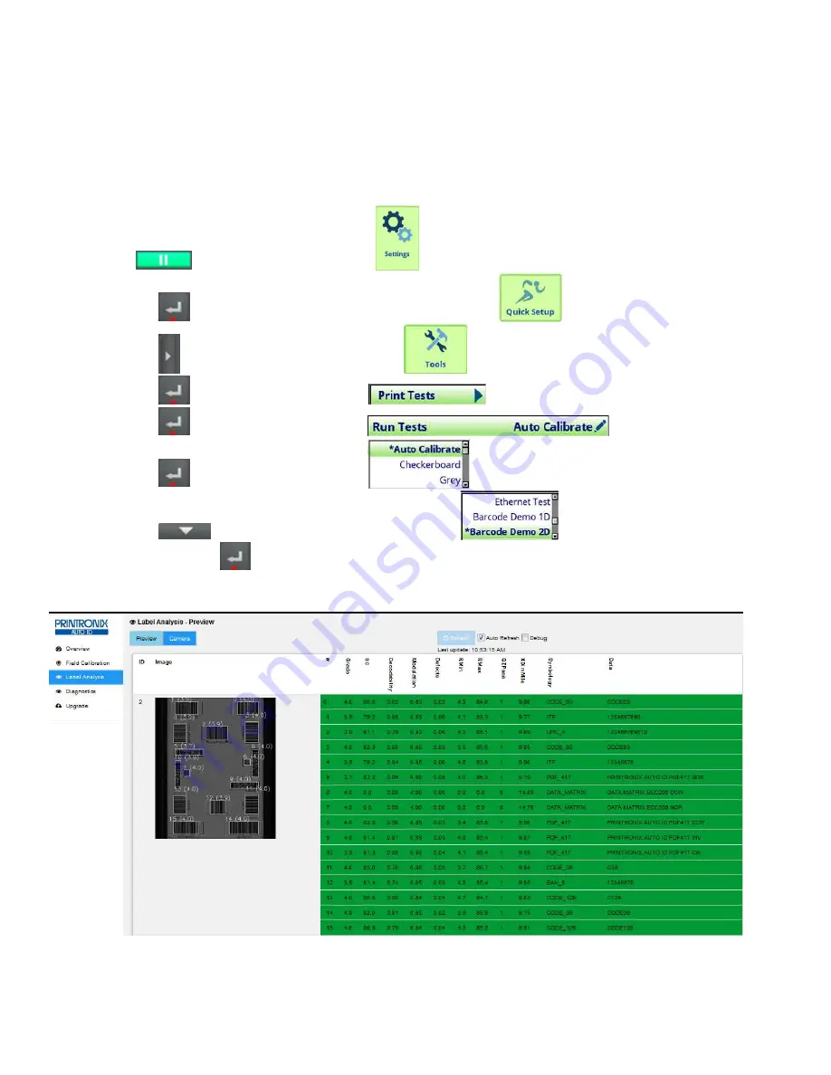
 key, and Barcode Demo 2D test pattern will begin to print a 1 Page 2D barcode image 

and grade it. 

NOTE:  

See (figure 40) below for screen image results. 


Figure 47: 

Proper Rectangle Alignment Around Barcodes & Barcode Grades Image 


Содержание Auto ID ODV2D-V2

Страница 1: ...1 ODV2D V2 Installation Instructions...

Страница 2: ...mbly 5 4 Install ODV2D V2 Interface PCBA and Cable 5 5 Installing ODV2D V2 and Mounting Bracket to Printer 11 6 Coarse Mechanical Alignment 13 7 Prepare for Alignment Calibration 17 8 Alignment 27 9 C...

Страница 3: ...ap for center line access hole Printronix Calibration Plaque P N P220237 001 spare P220292 001 Package of 4x6 inch Direct Thermal Liner Gap Fanfold Media Alcohol wipes P N P200016 002 Required Tools a...

Страница 4: ...Set the printer power switch to O Off Switch located on rear of printer WARNING Always unplug the printer power cord from the printer or the power outlet before doing any installation procedure Failu...

Страница 5: ...he kit to the front of the printer Secure the door to the printer with the two M5x16mm thumb screws provided Bias the door downwards while tightening the screws Figure 2 Install new Peel Tear plate us...

Страница 6: ...nted part of the printer frame Touch the frame with the hand wearing the wrist strap 4 Raise the media cover and remove the plastic plug from the frame opening and set it aside Figure 4 Removing the P...

Страница 7: ...ging its connector into J10 at the top right side of the Controller PCBA and its brass standoff into the mating hole in the Controller PCBA Figure 6 Installing the ODV2D V2 Interface PCBA J10 Controll...

Страница 8: ...vided in the kit Figure 7 Wrapping the Power Data Cable around the Ferrite Core 8 Plug the Power Data cable into J1 of the ODV2D V2 Interface PCBA Figure 8 Plugging the Power Data Cable into the ODV2D...

Страница 9: ...ing deck lock sensor cables then through the new wire saddle Lock the ends of the wire saddles to constrain the cables Secure the Ferrite Core to the wire saddle using a tie wrap CAUTION In step 9 rou...

Страница 10: ...DV Data Cable through large hole in frame next to ribbon motor 11 On the media side of the printer install Split Grommet over ODV Power Data Cable Squeeze and press into large hole on frame Figure 11...

Страница 11: ...essed area at the back of the unit Align the three holes on the mounting bracket with the threaded holes in the printer frame Thread the three M4x10mm flanged SHC screws provided and then use a 3mm he...

Страница 12: ...ng the Power Data Cable on the Bracket and into the Frame Opening 3 Route the Power Data cable between the printer frame and both ODV2D V2 bracket tabs shown in Figure 14 Make sure the cable is not pi...

Страница 13: ...cking and adjustment screws Set the cover aside Figure 15 Removing the Plastic Cover on the ODV2D V2 2 Place a 6 inch square between the ODV2D V2 and the mounting bracket to verify that the back of th...

Страница 14: ...ing bracket preventing the ODV2D from moving freely when the small locking screws are loosened 4 Then while holding the square in place See Figure 16 adjust Setscrew A CW using a 2mm hex key to move t...

Страница 15: ...Adjustment NOTE The bubble may NOT be centered in the level It is not necessary that the table the printer or the ODV2D be perfectly level only that the angles of these surfaces be match Figure 20 ODV...

Страница 16: ...to Figure 20 and do the following Use a 2mm hex key and turn Setscrew B CW to move the bubble to the right or CCW to move the bubble to the left NOTE After leveling the ODV2D V2 do not tighten any of...

Страница 17: ...cated on the rear of the printer 2 Turn the power switch located on the rear of the printer ON I position Control Panel Special Key s The image below displays the names of the special key s Soft Key 1...

Страница 18: ...the DOWN key to select Enable 9 Press the ENTER key to enter selection 10 Press PAUSE key to take printer ON LINE 11 Press the ENTER key to save Viewing Printer ODV2D V2 Software Versions NOTE It is...

Страница 19: ...il control panel displays ODV2D V2 system 2 Press the LEFT Soft Key 1 Menu Home to return to home menu 3 Press PAUSE key to take printer ON LINE 4 Contact Printronix Auto ID for the latest Printer and...

Страница 20: ...ontrol panel will display 7 Press the ENTER key control panel will display 8 Press the ENTER key control panel will display 9 Press the DOWN key until Grey is selected 10 Press the Press the ENTER key...

Страница 21: ...on DHCP 1 Refer to Dynamic Connection Ethernet Port for Lap Top setup WITH ROUTER Static Connection 2 Refer to Static Connection Ethernet Port for Lap Top setup NO ROUTER 3 Default IP Address 10 20 30...

Страница 22: ...ntil Statistics is selected 6 Press the ENTER key control panel will display 7 Press the UP key until IP Address is selected 8 Note the IP Address it will be used later in ODV2D V2 Calibration Example...

Страница 23: ...4 Press the LEFT ARROW until Media 5 Press the ENTER key control panel will display 6 Press the DOWN key until Handling is selected 7 Press the ENTER key control panel will display 8 Press the ENTER k...

Страница 24: ...will display 19 Press the UP key until Disable is selected 20 Press the ENTER key control panel will display 21 Press the left Soft Key 1 Menu Home to return to home menu 22 Press PAUSE key take print...

Страница 25: ...rol Panel to Print Bullseye Unlock Control Panel 1 Press PAUSE key to take printer OFF LINE panel will display Note If C P has been already un locked skip to Select Bullseye pattern now 2 Press UP and...

Страница 26: ...ap Figure 28 Bullseye Pattern Printout 8 Tear off any extra labels Leave only one label protruding from the printer exit Web Browsers NOTE Use the Chrome or Fire Fox web browser IE may not work correc...

Страница 27: ...They need to be set in the order shown The Height is factory set and should not need adjustment Tilt and Slope are set independently but may affect each other as one is changed the other may move too...

Страница 28: ...bias the ODV2D V2 straight up or down in the mounting holes until the dial reaches the Green Be careful not to touch the scan glass as you grip the ODV2D V2 assembly 2 Re tighten the three mounting sc...

Страница 29: ...alibration Target Figure 33 Slope Tilt Dials 3 Tilt 1 For the Tilt adjustment place the bubble level on the top of the ODV2D V2 to make sure it is the same as measured previously and turn the setscrew...

Страница 30: ...owly tighten the three small locking cap screws until secure keeping both of the settings in the green They do not need to be perfectly aligned with the zero 4 Center Line Adjustment Figure 35 Center...

Страница 31: ...iver or a 3mm hex wrench to turn the Adjustment Screw on the top of the ODV2D per the Right Hand Rule counter clockwise turn Center line goes up Clockwise turn Center line goes down until the dial sho...

Страница 32: ...he center position to the correct value When performing label analysis and if the boxes are not aligned around the barcodes this will be because of not pressing the save button Tap Test When unit is t...

Страница 33: ...Calibration Card should be placed in the scan line during calibration Media should be removed from the tear bar to prevent uneven calibration surface Remove the ribbon if it is installed 5 The Calibr...

Страница 34: ...all White Gain Calibration Card Figure 40 White Gain Calibration Image Web Page 3 Press Setup Camera button The following image should be displayed 4 Press Calibrate button and the following message w...

Страница 35: ...ibration SUCCESS message Reflectance Calibration Installing Barcode Calibration card 1 Press the Reflectance button Figure 43 Install Barcode Calibration Card 2 Install the barcode side of the calibra...

Страница 36: ...it s own value printed on it 5 Press Calibrate button The following message will be displayed Figure 45 Barcode Calibration in progress message 6 When the barcode calibration has finished the followin...

Страница 37: ...panel should display 3 Press the key until Tools have been selected 4 Press the key control panel will display 5 Press the key control panel will display 6 Press the key control panel will display 7 P...

Страница 38: ...able from the right side of the ODV and remove any special labels that were used to do the Field Calibration Install the required media and ribbon used to print labels and power On the printer If requ...

Страница 39: ...Sight Savers Lens Cleaner Spray or equivalent to clean the glass There are no serviceable parts within the ODV2D V2 assembly Replace any components that are damaged or not operating per the spares li...

Страница 40: ...g wrong with the LED array Call your service representative if the problem persists The printer pauses after scanning each label For complex labels with 2 D or several 1 D barcodes the printer might b...

Страница 41: ...to be calibrated Complete White Gain calibration on page 29 and Reflectance on page 32 Make sure the entire bar code passes completely under the scanning beam The validator and printer are not properl...

Страница 42: ...ge 22 If problems persist decrease the Media Speed Print Speed Be sure the bar code is not printing on the extreme edges of the label Clean the printhead See Cleaning in the Administrator s Manual Che...

Страница 43: ...te All examples below are for the Windows 7 operating system Control Panel Select Control Panel from START selection The followig screen will be displayed Select Network and Sharing Center as shown ab...

Страница 44: ...44 Select Change Adapter settings as shown above The following screen should be displayed Select Local Area Connection as shown above The following screen should be displayed...

Страница 45: ...45 Select the Properties button as shown above The following screen should be displayed Select Internet Protocol Version 4 TCP IPv4 as shown above The following screen should be displayed...

Страница 46: ...46 Select Use the following IP address as shown above The following screen will be displayed...

Страница 47: ...Address Enter Subnet Mask Enter Default Gateway Press OK button when done Close all open windows This completes the configuration process Return to Preparing the T8X04 Prior to Printing the Bullseye...

Страница 48: ...rol Panel from START selection The followig screen will be displayed Select Network and Sharing Center as shown above And the following screen will be displayed Select Change Adapter settings as shown...

Страница 49: ...49 Select Local Area Connection as shown above The following screen should be displayed Select the Properties button as shown above The following screen should be displayed...

Страница 50: ...4 as shown above The following screen should be displayed Select Obtain an IP address automatically as shown above The following screen will be displayed Close all windows Return to Preparing the T8X0...

Страница 51: ...lem with a new install or an existing printer Description of the problem be specific Good and bad samples that clearly show the problem faxing or emailing of these samples may be required Americas 844...

Страница 52: ...Fax 49 0 8106 37979 05 Printronix Auto ID Asia Pacific Head Office Taiwan 9F No 95 Minquan Rd Xindian Dist New Taipei City 231 Taiwan R O C Phone 886 3 990 6155 Fax 886 3 990 6215 Printronix Auto ID...

Отзывы: