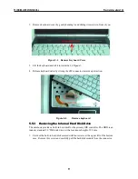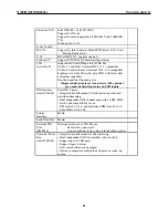
Figure 5-8 Removing the three screws on the bottom case
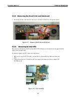
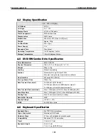
2. To remove the two screws and two hex-bolds of rear side for the system unit.
Figure 5-9 Two Screws and two hex-bolds
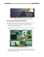
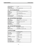
3. Removing the two screws of LCD connector and one LCD cable.
Figure 5-10 Two Screws and one LCD cable
2.
Slowly pullout the LCD panel from the system unit.
TECHNICAL SERVICE MANUAL
Prestigio Cavaliere 142
93
Содержание CAVALIERE 142
Страница 1: ...PRESTIGIO CAVALIERE 142 TECHNICAL SERVICE MANUAL...
Страница 107: ...w w w p r e s t i g i o c o m...

