


5.4.1 Cover-Display LCD assembly
The Cover-Display LCD Assembly includes the following major Field Replaceable
Units/parts (FRUs):
•
LCD Face and Back Panel Cover
These parts are used to cover the whole LCD Panel assembly, which includes the LCD
Display Module, the LCD FPC cables, and inverter board.
•
LCD Display Module
“
13.3
”
LCD (Liquid Crystal Display) screen is used for output display. This part is
assembled together with LCD Power Inverter Board, and LCD cables contained inside the
whole LCD Panel. Handle this part with care against static electricity and accidents that
can break the LCD.
•
LCD Power Inverter Board
This part or PCB (Printed Circuit Board) is used to provide high voltage to the CCFT
(Cold Cathode Fluorescent Tube) of the notebook
’
s LCD backlighting. It is connected to
the right side of the LCD display screen and attached to the back panel by a screw.
Exercise safety electrical precautions in handling and servicing this part. The circuit board
also includes the function for displaying the power status and battery charge LED
indicators.
•
LCD FPC Cable
The LCD FPC cable is used to convert output signals from the motherboard in driving the
LCD display screen. The cable is connected to the back of the LCD Panel.
5.4.2 System Unit Assembly
The System Unit Assembly comprise of several assemblies of which can be divided into two
major sub-assemblies.
•
The System Top Unit Assembly.
•
The System Base Unit Assembly.
The following System Top Unit Assembly includes the following major Field Replaceable
Units/parts (FRUs):
•
Glidepad Touch Pad Module Assembly
The touch pad (glide pad) pointing device module is assembled at the underside of the top
cover with the sensor pad exposed on the top. The assembly comprises of the glide pad
board, the glide pad converter board, the select buttons bracket casing, the insulator sheet,
the glide pad FPC cable, and the glidepad wire cable. The glide pad board is assembled
just underneath the select button assembly. It provides a FPC cable connector for the
mother board.
•
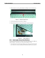
Keyboard Panel Assembly
The keyboard is assembled on top of the system unit and connected to the main board
’
s
keyboard FPC type connector. The keyboard is also secured on the system
’
s top unit
casing. There are no screws attached to the keyboard.
TECHNICAL SERVICE MANUAL
Prestigio Cavaliere 142
88
Содержание CAVALIERE 142
Страница 1: ...PRESTIGIO CAVALIERE 142 TECHNICAL SERVICE MANUAL...
Страница 107: ...w w w p r e s t i g i o c o m...


