P
RO
V
U
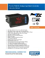
PD6210 Analog Input Batch Controller Instruction Manual
3
Table of Contents
Table of Contents ----------------------------------------- 3
Table of Figures ------------------------------------------- 3
Introduction ------------------------------------------------- 4
Ordering Information ------------------------------------ 5
Specifications ---------------------------------------------- 6
General ------------------------------------------------------------ 6
Process Input --------------------------------------------------- 6
Batch Controller Rate/Totalizer Display --------------- 7
Relays ------------------------------------------------------------- 7
Isolated 4-20 mA Transmitter Output ------------------- 8
RTU Serial Communications ----------------- 8
PDA1044 Digital Input & Output Expansion Module
----------------------------------------------------------------------- 8
MeterView Pro -------------------------------------------------- 8
Compliance Information -------------------------------- 9
Safety -------------------------------------------------------------- 9
Electromagnetic Compatibility ---------------------------- 9
Safety Information -------------------------------------- 10
Installation ------------------------------------------------ 10
Unpacking ------------------------------------------------------ 10
Panel Mounting Instructions ----------------------------- 10
Mounting Dimensions ------------------------------------ 11
Transmitter Supply Voltage Selection (P+, P-) ---- 11
Connections --------------------------------------------------- 12
Connectors Labeling -------------------------------------- 12
Power Connections --------------------------------------- 12
Signal Connections --------------------------------------- 13
Modbus RTU Serial Communications ---------------- 14
Relay Connections ---------------------------------------- 14
Switching Inductive Loads ------------------------------- 14
F4 Digital Input Connections ---------------------------- 15
4-20 mA Output Connections --------------------------- 15
Analog Output Transmitter Power Supply ----------- 15
External Relay & Digital I/O Connections ----------- 16
Interlock Relay Feature ---------------------------------- 16
Basic Operation and Programming --------------- 17
Front Panel Buttons and Status LED Indicators -- 17
Controller Operation ---------------------------------------- 18
Batch Control Operation Example --------------------- 19
Pro Software --------------------------------- 21
MeterView Pro Installation ------------------------------ 21
Display Functions and Messages ---------------------- 22
Setting Numeric Values ----------------------------------- 24
Setting Up the Batch Controller (
Scaling and Calibration ---------------------------------- 26
Setting the Totalizer and Batching Features (
----------------------------------------------------------------- 26
Setting the Input Units or Custom Tags (
Programming the Batch Controller (
) ------------------------------ 29
Setting the Display Parameter & Intensity (
----------------------------------------------------------------- 30
) ---------------------------- 32
Setting the Relay Action --------------------------------- 32
Setting Batch Control Relays --------------------------- 32
Programming Alarm Set and Reset Points --------- 33
Setting Fail-Safe Operation ----------------------------- 33
Programming Time Delay ------------------------------- 33
Relay Action for Loss of 4-20 mA Input (Loop Break)
----------------------------------------------------------------- 33
Relay Operation Details ----------------------------------- 34
Overview ----------------------------------------------------- 34
Relays Initialization --------------------------------------- 34
Fail-Safe Operation --------------------------------------- 34
Front Panel LEDs ----------------------------------------- 34
) ---------------------------------- 35
Pump Alternation Control -------------------------------- 35
Setting Up the Interlock Relay (Force On) Feature 35
Sample Relay Operation -------------------------------- 36
Relay and Alarm Operation Diagrams ---------------- 36
High Alarm Operation (Set > Reset) ------------------ 36
Low Alarm Operation (Set < Reset) ------------------ 36
High Alarm with Fail-Safe Operation (Set > Reset)
----------------------------------------------------------------- 36
Low Alarm with Fail-Safe Operation (Set < Reset) 36
Rate Relay Sampling Operation ----------------------- 37
Total Relay Sampling Operation ----------------------- 37
Signal Loss or Loop Break Relay Operation ------- 37
Time Delay Operation ------------------------------------ 38
Scaling the 4-20 mA Analog Output (
) ----------------------------------------- 39
) ------------------------------------- 39
Protecting or Locking the Controller ------------------ 39
Grand Total Reset Password & Non-Resettable
Total ---------------------------------------------------------- 40
Making Changes to a Password Protected
Controller ---------------------------------------------------- 40
Disabling Password Protection ------------------------ 40
Advanced Operation and Programming --------- 41
Advanced Features Menu & Display Messages --- 42
Function Keys Operation -------------------------------- 44
F4 Operation ------------------------------------------------ 44
Advanced Setup and Calibration ---------------------- 44
Maximum/Minimum Readings -------------------------- 44
) ------------------------------------- 45
) --------------------------- 45
) ------------------------------ 45
Modbus RTU Serial Communications (
) ------------------------------------ 46
Programmable Function Keys User Menu (
Troubleshooting ----------------------------------------- 50
) -------------------------------- 50
Determining Software Version ------------------------- 50
Reset Controller to Factory Defaults ----------------- 50
Factory Defaults & User Settings ---------------------- 51
Troubleshooting Tips -------------------------------------- 53
EU Declaration of Conformity ----------------------- 55

