background image

11

NT2-210018 Optical Spectrum 

Analyzer User Guide

6176 E. Molloy Rd. East Syracuse, NY 13057 U.S.A. • [email protected] • 1-800-800-6652 • +1 315-431-7200 • www.ppc-online.com

BELDEN 

BRAND

Optical Network

Solutions

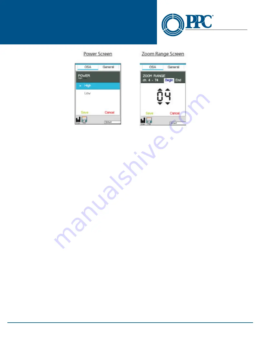
Fig 8.2

8.1 OSA Parameter Tab

Power Level

The NT2-210018 has two optical ports: a low power and high power port. The low power port is designed for 

maximum power of -10dBm per channel and a maximum composite power of +22dBm. The high power port is 

designed for a maximum of +10dBm per channel and a maximum composite power of +29dBm. Upon starting 

the NT2-210018, the switch Port dialog will be displayed to indicate the power setting. If the desired power level is 

indicated, connect the fiber under Test to the port shown and touch the screen or press the Select button to clear 

the dialog box. If the wrong power level is indicated, touch the screen to remove, then open the icon menu and 

select the Settings icon. Touch the Power setting in the Power Parameter screen, select the desired power and touch 

Save, then touch the Scan icon in the bottom left of the display to return to the Graph screen.

Note

The power may also be changed quickly by touching the green dBm scale at the top of the display to toggle 

between high and low power.

Resolution

The resolution may be set to 50 GHz (0.4 nm) or 100 GHz (0.8 nm) per channel, or High and Low resolution 

respectively. At high or low (50 or 100GHz) resolution, the first channel will be the first channel as established by 

the first channel setting in the General tab of the Settings screen.

View Setting

The view setting sets the view of the scan to total power or tilt monitoring. Total power is the power being 

introduced to the fiber. Tilt monitoring is used for both power tilt and gain tilt as described below. In the tilt 

monitoring setting, there will be a linear regression line on the display and the value associated with that regression 

line is displayed in the bottom right cell.

To display the tilt monitor, enter the Settings screen by bringing up the Icon menu and touching the Settings icon. 

Touch the View Setting and select Tilt Monitor. The tilt monitor is now turned on for power and gain tilt.

Power Tilt

Power Tilt, is displayed as a linear regression line overlaid on the graph and as a numeric indicator in the bottom 

right of the display. This reading only factors in the channels that are greater than the minimum power level of the 

scale. This can be used to assist with balancing the power of DWDM system. The flatter (more level) the line, or the 

closer to zero the power tilt number, the more balanced the power between channels.

Содержание NT2-210018

Страница 1: ...NT2 210018 Optical Spectrum Analyzer User Guide A BELDEN BRAND Optical Network Solutions...

Страница 2: ...ent it is highly suggested the user reads all safety information first This product has been designed and tested in accordance with the manufacturer s safety standards and has been supplied in a safe...

Страница 3: ...ructions on setting the power level Section 3 Quick Start Guide Press the POWER button to turn on the NT2 210018 Operation The port power setting dialog will be displayed It indicates the current powe...

Страница 4: ...desired Note Touching the left hand channel number bar is a quick method to switch to the table display and touching the left most channel number bar on the table display will revert back to the grap...

Страница 5: ...d to withstand the rigors of field use and are extremely user friendly Section 5 Preparation For Use 5 1 Inspection Before shipment this instrument was inspected and found to be in perfect working ord...

Страница 6: ...battery charger to rain or excessive moisture Do not use the AC adapter when there are signs of damage to the enclosure or cord Ensure you are using the correct charger for the local line voltage Do...

Страница 7: ...zer User Guide 6176 E Molloy Rd East Syracuse NY 13057 U S A customerservice ppc online com 1 800 800 6652 1 315 431 7200 www ppc online com A BELDEN BRAND Optical Network Solutions Top Plate Fig 6 2...

Страница 8: ...er User Guide 6176 E Molloy Rd East Syracuse NY 13057 U S A customerservice ppc online com 1 800 800 6652 1 315 431 7200 www ppc online com A BELDEN BRAND Optical Network Solutions 7 2 Touch Display G...

Страница 9: ...s accessed by touching the bottom of the display or pressing the Menu button To remove the menu from the bottom of the display either select an icon touch the display above the menu or press the Menu...

Страница 10: ...h it or press Select OSA and General Settings Pages Fig 8 1 Note The Directional buttons and the Select button are not operational in the Settings screen To select a parameter to be modified touch it...

Страница 11: ...the display to toggle between high and low power Resolution The resolution may be set to 50 GHz 0 4 nm or 100 GHz 0 8 nm per channel or High and Low resolution respectively At high or low 50 or 100GHz...

Страница 12: ...the Select button on the keypad Do not use the Select icon on the file manage ment screen Enter file management again and with OSA tab highlighted move the file to be compared to the highlighted bar...

Страница 13: ...requency to match that of the system channels save and touch the Scan icon in the bottom left of the display to return to the graph screen NOTE It s important to note that this prevents reading channe...

Страница 14: ...strument s capabilities at minimum and at worst result in the need to return the NT2 210018 to the factory for expensive repairs Prior to making any connection to the unit ensure that all proper clean...

Страница 15: ...d shifts the scale accordingly This scale is also modified when Zoom is selected It shifts the number of channels as selected with the zoom feature If zoom was set to see only channels 51 60 it would...

Страница 16: ...ment To move a cursor touch anywhere between the channel number column and the cursor point column and the active cursor will snap to the channel selected To slide the cursor up and down on the displa...

Страница 17: ...n the keypad or touch the File icon on the display 10 1 File Management Display Main File Management Screen OSA Folder Fig 10 1 Configuration and Scope Folder Displays Fig 10 2 NT2 210018 Optical Spec...

Страница 18: ...down the file list until the next file to be marked is highlighted and touch Mark select again The Mark select is a toggle and to unmark a file place it in the highlighted position and touch Mark sele...

Страница 19: ...t software running touch the Upload icon and the files will transfer to the selected folder on the computer Note Config files cannot be transferred to the CertSoft software Section 11 Video Scope Oper...

Страница 20: ...mode there will be a highlight around one of the icons on the top or the bottom of the display Note Touching icons on the video scope screen will put the unit into Menu mode and activate or toggle the...

Страница 21: ...Connector Image Once the image is stable and focused use the stylus to touch the approximate center of the connector to snap the image near the center of the display and the center of the grading ring...

Страница 22: ...uick Save icon to record the information Note Marking the points of contamination should be done last just before saving the image Once the unit is re turned to live mode the markers are removed Exiti...

Страница 23: ...expose the battery charger to rain or excessive moisture Do not use the AC adapter when there are signs of damage to the enclosure or cord Ensure you are using the correct charger for the local line v...

Страница 24: ...at the port needs to be cleaned the first step is to be certain the instrument is off We suggest the use of isopropyl alcohol and foam swabs specifically designed for cleaning connectors accepting 2 5...

Страница 25: ...ions and a return authorization number RMA Section 15 Trouble Shooting Guide NT2 210018 Troubleshooting Symptom Possible Cause Solution LCD dark Power not on Press ON OFF key Batteries require recharg...

Страница 26: ...k Solutions Section 16 Version Control Through a program of continuous improvement we upgrade the features and performance of the instrument in an ongoing process The instrument firmware version is ac...

Отзывы: