background image

2

Power-Flo Pumps & Systems • 877-24PUMPS • www.powerflopumps.com

General Safety Information

® Power-Flo  is a registered trademark of Power-Flo Technologies Inc.

Other brand and product names are trademarks or registered trademarks of their respective holders.

Alteration Rights Reserved. 

7/08, 7/09, 9/09, 4/10, 7/10, 12/10, 4/14, 11/14, 8/17, 9/2020, 1/2021

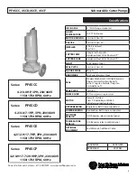
PF4SCC, 4SCD, 4SCE, 4SCF    


 Submersible Cutter Pumps

Before installation, read the following 
instructions carefully. Failure to follow 
instruction and Safety information could 
cause serious bodily injury, death and/or 
property damage. Each Power-Flo pump is 
individually factory tested to insure proper 
performance. Closely following these 
instructions will eliminate potential operating 
problems, assuring years of trouble-free 
service.

                                           “

Danger” indicates


        an imminenty 

hazardous situation which, if not avoided, 

WILL result in death or serious injury.

                                                 “Warning” indicates


        an imminenty 

hazardous situation which, if not avoided, 

MAY result in death or serious injury.


        “Caution”  indicates


         an potentially 

hazardous situation which, if not avoided, 

MAY result in minor or moderate injury.

IMPORTANT - Power-Flo Pumps and 

Systems is not responsible for losses, injury 

or death resulting from failure to observe 

these safety precautions, misuse, abuse or 

misapplication of pumps or equipment.

 ALL


RETURNED 

 PRODUCTS MUST BE
 CLEANED, SANITIZED,
 OR RECONTAMINATED
 PRIOR TO SHIPMENT, TO 

INSURE EMPLOYEES WILL NOT BE EXPOSED 
TO HEALTH HAZARDS IN HANDLING SAID 
MATERIAL. ALL APPLICABLE LAWS AND 
REGULATIONS SHALL APPLY.


       Installation, wiring,


       and junction 

connections must be in accordance with 
the National Electric Code and all applicable 
state and local codes. Requirements may 
vary depending on usage and location.


        Installation and


        servicing is to be 

conducted by qualified personnel only.


        Keep clear of suction


       and discharge

 openings. 

Do not

 insert fingers in 

 pump with power connected.


     The cuting mechanism 

is  


VERY SHARP!


 Be extremely careful when
 servicing and or repairing the
 pump.


       Always wear eye


       protection when 

working on pumps. Do not wear loose 
clothing that may become entangled in 
moving parts


 Pumps build up heat 


      and pressure during

 operation. Allow time

 for pumps to cool 

 before handling or
 servicing. 


      This pump is 

not


      intended for use

 in swimming pools or water 
 installations where human 
 contact with pumped fluid. 


       Risk of electric shock. 


       To reduce risk of 

  electric shock, always disconnect 
  pump from power source before 
  handling. 

Lock out power & tag.


Do not

 us these 


       pumps in water 

over 104˚F. 

Do not

 exceed manufactures 

recommended maximum performance, as 
this could cause the motor to overheat.


Do not

 lift, carry or 


      hang pump by the

 electrical cables. Damage to the
 electrical cables can cause shock,
 burnes or death. 

Never

 handle 

connected power cords with wet hands. Use 
appropriate lifting device.


      Sump and sewage 


      pumps often handle 

materials which could cause illness or disease. 
wear adequate protective clothing when 
working on a used pump or piping. Never 
enter a basin after it has been used.


      Failure to permanently


      ground the pump, 

 motor and controls before

 connecting to power can cause

 shock, burns or death.


        These pumps are 

NOT


 to be installed in

 locations classified as hazardous in

 accordance with the National 

 Electric Code, ANSI/NFPA 70.


       Bronze/brass fitted 


       pumps may contain

 levels higher than considered

 safe for potable water systems.

 Government agencies have

  determined that leaded copper 

alloys should not be used in 

potable water applications.

IMPORTANT!

Prior to installation, record Model 

Number, MFG Date, Amps, Voltage, Phase 

and HP, from pump name plate for future 

reference. Also record the Voltage and 

Current Readings at Startup:

1 Phase Models

Amps:

Volts:

3 Phase Models

Amps L1-2:

Volts L1-2:

Amps L2-3:

Volts L2-3:

Amps L3-1:

Volts L3-1:

Model Number: ____________________

MFG Date: ____________

PHASE: ______ HP: _________________

WARNING: 

CANCER AND REPRODUCTIVE HARM-

WWW.P65WARNINGS.CA.GOV

Содержание PF4SCC Series

Страница 1: ...SCF 4 2 8 9 17 7 29 9HP 3PH 230 460V 1150 1750 RPM 60 Hz Series PF4SCC 4 2 4 8HP 3PH 230 460V 1150 1750 RPM 60 Hz Series PF4SCD 4 2 4 8 7 1HP 3PH 230 460V 1150 1750 RPM 60 Hz Series PF4SCE 4 2 12 9 17...

Страница 2: ...gers in pump with power connected The cuting mechanism is VERY SHARP Be extremely careful when servicing and or repairing the pump Always wear eye protection when working on pumps Do not wear loose cl...

Страница 3: ...nless Steel SEAL Tandem Mechanical Oil Filled Reservoir Upper Carbon Stainless Buna N Lower Tungsten Carbide Tungsten Carbide Buna N SEAL PLATE Cast Iron POWER CORD 30 ft cord pressure grommet MOTOR N...

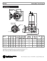
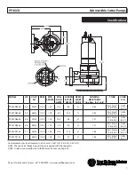
Страница 4: ...0 457 0 57 PF4SCC4246 4 2 460 3 1150 100 6 4 31 5 2 45 G 4G1 5mm2 14 4 SO 0 457 0 57 PF4SCC4834 4 8 230 3 1750 100 14 4 80 1 21 H 4G1 5mm2 14 4 SO 0 457 0 57 PF4SCC4844 4 8 460 3 1750 100 7 2 40 1 21...

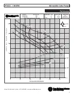
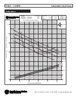
Страница 5: ...5 Power Flo Pumps Systems 877 24PUMPS www powerflopumps com Performance PF4SCC 1150 RPM Submersible Cutter Pumps...

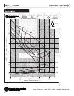
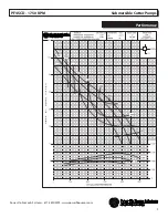
Страница 6: ...6 Power Flo Pumps Systems 877 24PUMPS www powerflopumps com PF4SCC 1750 RPM Submersible Cutter Pumps Performance...

Страница 7: ...SCD4834 4 8 230 3 1750 100 14 4 80 H 1 21 4G1 5mm2 14 4 SO 0 453 0 57 PF4SCD4844 4 8 460 3 1750 100 7 2 40 H 1 21 4G1 5mm2 14 4 SO 0 453 0 57 PF4SCD7134 7 1 230 3 1750 100 19 4 114 H 1 65 4G1 5mm2 14...

Страница 8: ...8 Power Flo Pumps Systems 877 24PUMPS www powerflopumps com PF4SCD 1150 RPM Submersible Cutter Pumps Performance...

Страница 9: ...9 Power Flo Pumps Systems 877 24PUMPS www powerflopumps com PF4SCD 1750 RPM Submersible Cutter Pumps Performance...

Страница 10: ...SCE12934 12 9 230 3 1750 132 35 4 230 J 0 48 4G6mm2 10 4 SO 0 67 0 75 PF4SCE12944 12 9 460 3 1750 132 17 7 115 J 0 48 4G6mm2 10 4 SO 0 67 0 75 PF4SCE17734 17 7 230 3 1750 132 45 8 292 H 0 41 4G6mm2 10...

Страница 11: ...11 Power Flo Pumps Systems 877 24PUMPS www powerflopumps com PF4SCE 1150 RPM Submersible Cutter Pumps Performance...

Страница 12: ...12 Power Flo Pumps Systems 877 24PUMPS www powerflopumps com PF4SCE 1750 RPM Submersible Cutter Pumps Performance...

Страница 13: ...CF8946 8 9 460 3 1150 132 12 8 75 H 0 64 4G6mm2 8 4 SO 0 67 0 78 PF4SCF17734 17 7 230 3 1750 132 45 8 292 H 0 41 4G6mm2 8 4 SO 0 67 0 78 PF4SCF17744 17 7 460 3 1750 132 22 9 146 H 0 41 4G6mm2 8 4 SO 0...

Страница 14: ...14 Power Flo Pumps Systems 877 24PUMPS www powerflopumps com PF4SCF 1150 RPM Submersible Cutter Pumps Performance...

Страница 15: ...15 Power Flo Pumps Systems 877 24PUMPS www powerflopumps com PF4SCF 1750 RPM Submersible Cutter Pumps Performance...

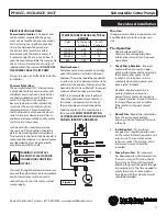
Страница 16: ...id level should never be less than above the pump s volute See Figure 1 ThecutterpumpsareNOTdesignedtorun dry ThecasingMUSTbesubmerged Installation The cutter pumps can be installed in a wet well util...

Страница 17: ...e Sensor To detec any moisture present a normally open N O probe is installed in the seal chamber The probe should be connected in series to an alarm device or motor starter coil to alert the operator...

Страница 18: ...t electrical power to pump Disassembly Cutter Impeller Remove cap screws 45 and washer 47 from volute 40 Lift motor from volute 40 Clean out volute and check impeller for pitting or wear To replace im...

Страница 19: ...USE IDENTIFICATION TAG ON EACH LEAD FIGURE 4 THREE PHASE 230 VOLT AC Power Cable Motor Lead Number G Ground G L1 or W1 1 7 L2 or W2 2 8 L3 or W3 3 9 T4 T5 T6 Together FIGURE 4 THREE PHASE 460 VOLT AC...

Страница 20: ...ain it is seated in the retainer and not cocked or resting on bellows tail Slide retaining ring 10D over shaft and let rest on spring 10C Upper Seal Clean and oil seal cavity in bearing bracket 3 Ligh...

Страница 21: ...Slide lower bearing and motor assembly into the bearing bracket 3 until bearing seats on the bottom Position bearing cap on some models on bearing bracket insert screws 19 with washers 20 and tighten...

Страница 22: ...flopumps com Figure 6 Repair Parts For Repair Part Please supply Model Number and MFG Date as shown on Name Plate and Part Description and Part Number as shown on Parts List PF4SCC 4SCD 4SCE 4SCF 100...

Страница 23: ...UMPS www powerflopumps com Repair Parts For Repair Part Please supply Model Number and MFG Date as shown on Name Plate and Part Description and Part Number as shown on Parts List PF4SCF 180 Mtr Frame...

Страница 24: ...dia 26 1 Screw H M4 x 6 H M4 x 6 H M4 x 6 27 1 Washer M 4 N M 4 N M 4 N 29 1 Power cable PF0 1852301 11X4G1 5 PF0 1852322 4G6 PF0 1852341 4G10 30 1 Ground 31 3 Wire connector 32 2 Cable connector PF0...

Страница 25: ...rt Please supply Model Number and MFG Date as shown on Name Plate and Part Description and Part Number as shown on Parts List PF4SCC 4SCD 4SCE 4SCF Submersible Cutter Pumps Cutter Impeller item 41 Imp...

Страница 26: ...26 Power Flo Pumps Systems 877 24PUMPS www powerflopumps com PF4SCC 4SCD 4SCE 4SCF Submersible Cutter Pumps Notes...

Страница 27: ...hree phase reverse any two of three power supply leads to ensure proper impeller rotation 11 Repair fixtures as required to eliminate leakage 12 Check pump temperature limits and fluid temperature 13...

Страница 28: ...od that has not been installed operated or maintained in accordance with Manufacturer s installation instructions that has been exposed to outside substances including but not limited to the following...

Отзывы: