20
Power-Flo Pumps & Systems • 877-24PUMPS • www.powerflopumps.com
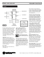
Remove retaining ring (10D), spring (10C)
and rotating member (10B) from shaft
(See Figure 5). Inspect seal for signs of
uneven wear pattern on stationary, chips
and scratches on either face.
DO NOT
interchange seal components, replace
the entire shaft seal (10). If replacing
seal, remove stationary (10A) from
intermediate (2) by prying out with flat
screw driver.
Upper Seal -
Remove screws (17),
washers (18) and intermediate (2) from
motor housing (1). Do not damage o-ring
(21) or sensor probe (36). Remove snap
ring (25), retaining ring (9D), spring (9C)
and rotating member (9B) from shaft. If
replacing seal, remove stationary (9A)
from bearing bracket (3) by prying out
with flat screw driver.
Reassembly:
Lower seal - Clean and oil seal cavity in
intermediate (2).
Lightly oil (
The use of grease is
NOT recommended
) outer surface
of stationary member (10A), press
stationary member (10A) firmly into
intermediate (2) using a seal tool,
nothing but the seal tool is to come in
contact with seal face.
Important! Hammering on the
seal pusher will damage the seal
face.
Make certian the stationary member is
in straight and that the rubber ring is
not out of it’s groove. Lightly oil (
The use
of grease is NOT recommended
), shaft
and inner surface of bellows on rotating
member (10B). With lapper surface facing
intermediate (2), slide rotating member
(10B) onto shaft using the seal tool
until lapped faces of (10B) and (10A) are
together.
Place spring (10C) over shaft and in
place on rotating member (10B) making
certain it is seated in the retainer and not
cocked or resting on bellows tail. Slide
retaining ring (10D) over shaft and let
rest on spring (10C).
Upper Seal - Clean and oil seal cavity
in bearing bracket (3). Lightly oil (
The
use of grease is NOT recommended
)
outer surface of stationary member (9A),
press stationary member (9A) firmly
into bearing bracket (3), using seal tool,
nothing but the seal tool is to come in
contact with seal faces. Be certain the
stationary member is in straight and that
the rubber ring is not out of it’s groove.
Lightly oil (
The use of grease is NOT
recommended
) the shaft and inner
surface of bellows on rotating member
(9B). With lapped surface facing bearing
bracket (3), slide rotating member (9B)
onto shaft, using seal tool until lapped
faces of (9B) and (9A) are together. Place
spring (9C) over shaft and in place on
rotating member (9B), being certain it
is seated in retainer and not cocked or
resting on bellows tail. Slide retaining
ring (9D) over shaft and let rest on spring
(9C) and replace snap ring (25) onto
shaft.
Motor & Bearing Service:
Bearings -
Slide motor assembly from
motor housing (1). Remove bearing (12)
from motor shaft using a wheel puller.
Remove snap ring (8) or screws (19)
with washers (20) and bearing bracket
(3). Remove snap ring (15) from shaft.
Remove bearing (11) from shaft, if
required, using a wheel puller.
Bearing Reassembly
- Be careful Not to
damage the rotor or the shaft threads.
On some models
, first slide bearing cap
(4) onto shaft. Apply adhesive compound
to the shaft and press lower bearing (11)
on the motor shaft.
Service
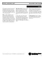
Figure 5
PF4SCC, 4SCD, 4SCE, 4SCF
Submersible Cutter Pumps
Note:
Upper stationary as
shown for 100Fr Mtrs
only, 132Fr & 180Fr Mtrs
have design similar to
stationary on lower seal.

