PDC 2000/3000 Repair Manual
Parts Replacement
91
Power Supply/Strobe Board Removal
1. Remove the top cover.
2. Remove the front end board.
3. Loosen, but do not remove the optics module.
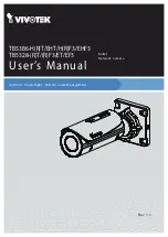
4. Disconnect the back end board cable from the power supply/strobe board connector
(Figure 5-9.)
Figure 5- 9. Removing power supply/strobe board
5. Guide the power supply/strobe board assembly out from under the optics module and free
of the camera chassis.
Note: The two guide pins which are used to properly align the board in the chassis.
Front End Board
Back End Board Cable
Power Supply/
Strobe Board
Hard Drive
(PDC2000 Only)
IDE Board
(PDC3000 Only)