CLUTCH
6.22
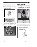
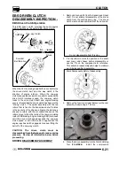
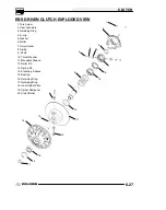
cylinder of the holding tool on top of the spider
assembly and retaining ring. Install the clutch
holding tool handle and slowly compress the
spider onto the shaft. Push helix inward. Remove
snap ring (A).
A
5. Remove the spider assembly, spring (B), and
spacer washer (C).
NOTE:
The spring is a
compression spring only and has no torsional
wind
B
C
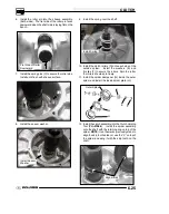
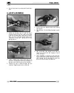
SPIDER DISASSEMBLY
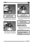
6. Remove the inside spider plate (D) and spider
dampener (E). Inspect the spider dampener (E)
for wear and replaced if needed.
E
D
7. Remove the E--clip (F), washer (G), and the
clutch rollers (H). Inspect the rollers for wear
replace if worn.
F
G
H
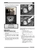
8. Remove the clutch assembly from the holding
tool. Remove the large outer retaining ring (I) and
the inner retaing ring (J).
I
J
Содержание Sportsman 800 Efi 2005
Страница 116: ...ENGINE 3 62 NOTES ...
Страница 136: ...FUEL SYSTEM FUEL INJECTION 4 20 NOTES ...
Страница 186: ...CLUTCH 6 30 NOTES ...
Страница 256: ...BRAKES 9 24 NOTES ...
Страница 292: ...ELECTRICAL 10 36 BASIC WINCH WIRING 2005 ATV MODELS 2005 ATV WINCH WIRING DIAGRAM ...
Страница 300: ...ELECTRICAL 10 44 NOTES ...
Страница 301: ...ELECTRICAL 10 39 WIRING DIAGRAM 2005 SPORTSMAN 700 800 EFI Stator ...
Страница 302: ...ELECTRICAL 10 40 WIRING DIAGRAM 2005 SPORTSMAN 700 800 EFI ...


