background image

ENGINE

3.39

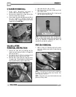
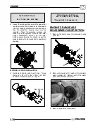
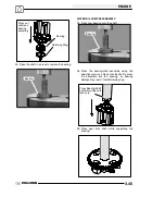
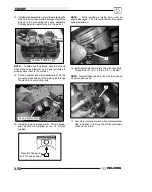
4. Install Flywheel Puller (

PN 2871043

) and remove

flywheel (F).

CAUTION:

Do not thread the puller

bolts into the flywheel more than 1/4

or stator

coils may be damaged.

2871043

F

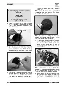
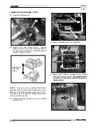
5. Remove the starter bendix (G), wire holddown

plate (H), and the woodruff key (I) from the

crankshaft. The stator does not have to be

removed at this point.

G

I

H

6. Remove the gear/stator housing bolts and

remove the gear/stator housing cover (J) and

gasket from the crankcase. Be sure to catch the

excess oil from the crankcase.

J

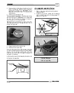
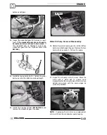
7. Note the positions of the gears in the photo.

Crank Gear

Counterbalance Gear

Camshaft Gear

8. Use a white pen to accent the timing marks on the

following gears: camshaft gear (K), crankshaft

gear (M), or counterbalance gear (N) This will

ensure proper gear alignment and timing during

reassembly of the gears.

Timing Marks

K

M

N

Water Pump Gear

Содержание Sportsman 800 Efi 2005

Страница 1: ...2005 SPORTSMAN 700 EFI 2005 SPORTSMAN 800 EFI SERVICE MANUAL PN 9919820 2005 SPORTSMAN 700 800 EFI SERVICE MANUAL PN 9919820 Printed in USA 9919820 PART Cvr_9919820 10 14 04 10 19 AM Page 1 ...

Страница 2: ...ations for Polaris Sportsman 700 800 EFI ATVs Comments or suggestions about this manual may be directed to Service Publications Dept Polaris Sales Inc 2100 Hwy 55 Medina Minnesota 55340 Some Polaris factory manuals can be downloaded from www polarisindustries com or purchased from www purepolaris com or contact your nearest Polaris dealer 2005 Sportsman 700 800 EFI ATV Service Manual PN 9919820 EC...

Страница 3: ...g the ATV CAUTION A CAUTION indicates special precautions that must be taken to avoid personal injury or ATV or property damage NOTE A NOTE provides key information to clarify instructions Trademarks Polaris acknowledges the following products mentioned in this manual Loctite Registered Trademark of the Loctite Corporation STA BIL Registered Trademark of Gold Eagle Nyogel Trademark of Wm F Nye Co ...

Страница 4: ...GENERAL MAINTENANCE ENGINE ELECTRONIC FUEL INJECTION CLUTCHING FINAL DRIVE BODY AND STEERING TRANSMISSION BRAKES ELECTRICAL ...

Страница 5: ...FI Dimensions 1 3 Specifications Sportsman EFI 1 4 1 5 Publication Numbers 1 6 Paint Codes 1 6 Replacement Keys 1 6 Standard Torque Specifications 1 6 Special Tools 1 7 1 10 Torque Table 1 11 Conversion Table 1 12 Tap Drill Charts 1 13 Decimal Equivalent Chart 1 13 Glossary of Terms 1 14 Specs ...

Страница 6: ...gine Emissions Model Year Plant No Individual Serial No Body Style Check Digit World Mfg ID This could be either a number or a letter ENGINE SERIAL NUMBER LOCATION Be sure to refer to the engine model number and serial number whenever corresponding about an engine This information can be found on the sticker applied to the top side of the crankcase A An additional number is stamped on the side of ...

Страница 7: ...k Capacity 200 lbs 90 7 kg Towing Capacity 1500 lbs 454 kg Hitch Tongue Capacity 150 lbs 68 kg Body Style Spirit MODEL 2005 SPORTSMAN 800 EFI MODEL NUMBER A05MH86AU ENGINE MODEL EH076OLE011 Category Dimension Capacity Length 83 in 205 74 cm Width 48 in 116 8 cm Height 48 in 119 4 cm Seat Height 34 in 86 4 cm Wheel Base 50 75 in 128 9 cm Dry Weight 770 lbs 326 6 kg Gross Vehicle Weight 1220 lbs 553...

Страница 8: ...Circuit Breakers Fan 20 amp Harness 20 amp Fuel pump ECU 15 amp Instrument Cluster Voltage Regulator 6 amp Starting Electric Instrument Cluster LCD Drivetrain Transmission Type Drumshift H L N Rev Park Transmission Capacity 15 oz 450m Rear Gearcase Capacity 5 oz 150ml Front Gearcase Capacity 5 oz 150ml Gear Ratio Low Rev High Front Drive Rear Drive 7 49 1 5 11 1 2 70 1 3 82 1 3 10 1 Clutch Type PV...

Страница 9: ...id 30 Amp Hr Circuit Breakers Fan 20 amp Harness 20 amp Fuel pump ECU 15 amp Instrument Cluster Voltage Regulator 6 amp Starting Electric Instrument Cluster LCD Drivetrain Transmission Type Drumshift H L N Rev Park Transmission Capacity 15 oz 450m Rear Gearcase Capacity 5 oz 150ml Front Gearcase Capacity 5 oz 150ml Gear Ratio Low Rev High Front Drive Rear Drive 7 49 1 5 11 1 2 70 1 3 82 1 3 10 1 C...

Страница 10: ...ARIS NUMBER Frame Black 9440 P 067 FRAME COLOR All P067 Medium Gloss Black 9440 8520147 Order direct at www polarisdealers com dealers only Mix as directed REPLACEMENT KEYS Replacement keys can be made from the original key To identify which series the key is take the first two digits on the original key and refer to the chart to the right for the proper part number Should both keys become lost ig...

Страница 11: ... Standard Tools and Engine Tools PU 45432 Caliper or A Basic Caliper Basic Micrometer 2871043 Flywheel Puller 2870773 C Clip Install Tool 2870386 Piston Pin Puller 2871445 Piston Pin Puller Adapter Standard Tools and Engine Tools 2870390 Piston Support Block PV 43527 Oil Filter Wrench PA 44995 Water Pump Mechanical Seal Install Tool PU 45543 Universal Driver Handle PA 45483 Main Seal Installer PA ...

Страница 12: ...r 2870588 Hone Oil 12 oz PV 35667 A Cylinder Leak down Tester 2200634 Valve Seat Reconditioning Kit Clutch PVT Tools 2870506 Drive Clutch Puller 2870913 Driven Clutch Puller 2872292 EBS Clutch Align Tool 9914177 A Drive Clutch Holding Tool 8700220 Clutch Compression Tool 2871358 Clutch Hold Fixture 2870341 Drive Clutch Spider Removal Tool ...

Страница 13: ...placement Kit 2870338 Spider Nut Socket 2871358 Clutch Holding Fixture 2871025 Clutch Bushing Replace Tool Kit Suspension Tools 2870871 ATV Ball Joint Tool Kit 2871071 Shock Body Holding Tool 2870623 Shock Spring Compressor 2871572 Strut Rod Wrench 2871573 2871574 Strut Spring Compressor 8700225 8700226 CV Boot Clamp Pliers ...

Страница 14: ...ectrical Tools PV 43568 Fluke 77 Multimeter PV 39617 Current Clamp 2870836 Battery Hydrometer 8712500 Tachometer RPM PV 39951 A Tachometer Electrical Tools 2870630 Timing Light 2871745 Static Timing Light Harness 2460761 Hall Sensor Probe Harness PV 39991 Peak Reading Adapter PV 37453 Christie Se Sulfating Multi Battery Charger PV 63070 Christie Multi Battery Charger ...

Страница 15: ...4 27 3 1 43 5 0 60 6 9 10 32 31 3 6 49 5 6 68 7 8 Torque ft lbs Nm 1 4 20 5 7 8 11 12 16 1 4 28 6 8 10 14 14 19 5 16 18 11 15 17 23 25 35 5 16 24 12 16 19 26 29 40 3 8 16 20 27 30 40 45 62 3 8 24 23 32 35 48 50 69 7 16 14 30 40 50 69 70 97 7 16 20 35 48 55 76 80 110 1 2 13 50 69 75 104 110 152 1 2 20 55 76 90 124 120 166 Metric 6 x 1 0 72 78 In lbs 8 x 1 25 14 18 ft lbs 10 x 1 25 26 30 ft lbs To c...

Страница 16: ...ubic centimeters cc x 0 061 Cubic inches cu in Imperial pints Imp pt x 0 568 Liters l Liters l x 1 76 Imperial pints Imp pt Imperial quarts Imp qt x 1 137 Liters l Liters l x 0 88 Imperial quarts Imp qt Imperial quarts Imp qt x 1 201 US quarts US qt US quarts US qt x 0 833 Imperial quarts Imp qt US quarts US qt x 0 946 Liters l Liters l x 1 057 US quarts US qt US gallons US gal x 3 785 Liters l Li...

Страница 17: ...6 11 32 R 3 8 13 32 13 32 0 0995 0 0937 0 1285 0 125 0 166 0 161 0 196 0 234 0 277 0 265 0 3125 0 3125 0 3437 0 339 0 375 0 406 0 406 3 32 3 32 1 8 1 8 11 64 5 32 13 64 15 64 9 32 17 64 5 16 5 16 11 32 11 32 3 8 13 32 13 32 DECIMAL EQUIVALENTS 1 64 0156 1 32 0312 1 mm 0394 3 64 0469 1 16 0625 5 64 0781 2 mm 0787 3 32 0938 7 64 1094 3 mm 1181 1 8 1250 9 64 1406 5 32 1563 4 mm 1575 11 64 1719 3 16 1...

Страница 18: ...t the end of a lever one meter in length applied in a rotational direction l or ltr Liter Left Side Always referred to based on normal operating position of the driver m Meter meters Mag Magneto Magnetic Induction As a conductor coil is moved through a magnetic field a voltage will be generated in the windings Mechanical energy is converted to electrical energy in the stator mi Mile miles mm Milli...

Страница 19: ...ry Maintenance 2 16 2 17 Ignition 2 17 Coolant System Maintenance 2 18 2 20 Radiator Screen Removal 2 20 Air Filter Service 2 20 2 21 Air Box Sediment Tube Service 2 21 Breather Filter 2 21 2 22 PVT Drying PVT Drain Plug 2 22 Oil Change Filter 2 23 2 24 Steering and Toe Alignment 2 25 2 27 Exhaust System Maintenance 2 27 2 28 Brake System Service 2 28 2 29 Suspension Service 2 29 2 30 Controls 2 3...

Страница 20: ...oil level begins to rise Monitor the oil level and if it continues to rise discontinue use and determine the cause or see your dealer Maintenance Chart Key The following symbols denote potential items to be aware of during maintenance H CAUTION Due to the nature of these adjustments it is recommended this service be performed by an authorized Polaris dealer SEVERE USE ITEM If vehicle is subjected ...

Страница 21: ...ry 2 years Headlamp tail lamp Daily Check operation apply dielectric grease if re placing E Air filter main element Weekly Inspect replace as needed Recoil housing if applicable Weekly Drain water as needed check often if operating in wet conditions J Brake pad wear 10 H Monthly 60 100 Inspect periodically Battery 20 H Monthly 125 200 Check terminals clean test Front gearcase oil if equipped 25 H ...

Страница 22: ...Throttle Cable ETC Switch 50 H 6 M 310 500 Inspect adjust lubricate replace if necessary E Air intake ducts flange 50 H 6 M 310 500 Inspect ducts for proper sealing air leaks Drive belt 50 H 6 M 310 500 Inspect adjust replace as needed Cooling system if applicable 50 H 6 M 310 500 Inspect coolant strength seasonally pressure test system yearly E Engine oil change 100 H 6 M 620 1000 Perform a break...

Страница 23: ...ect replace as needed J E Ignition Timing 100 H 12 M 620 1000 Inspect Wiring 100 H 12 M 620 1000 Inspect for wear routing security apply dielectric grease to connectors subjected to water mud etc J Clutches drive and driven 100 H 12 M 620 1000 Inspect clean replace worn parts J Front wheel bearings 100 H 12 M 1000 1600 Inspect replace as needed J Brake fluid 200 H 24 M 1240 2000 Change every two y...

Страница 24: ...arcase Front Drive Shafts Right Side View Transmission Rear Storage Compartment Front Storage Compartment Rack Gas Cap Gear Shifter Brake Lever Ignition Key EFI Diagnostic Plug Cover Brake Fluid Reservoir Instrument Cluster Speedometer Light Control Run Switch Reverse Override Throttle AWD Switch Work light Oil Dipstick Muffler Auxiliary Brake ...

Страница 25: ...tenance Kits can be purchased at your local Polaris dealer 2202166 Sportsman 600 700 Oil Change Kit Oil Filter 2 Qts of 0W 40 oil Instruction Sheet 2859066 Sportsman 600 700 Maintenance Kit Oil Filter 2 Qts of 0W 40 oil Drive Belt PVT Cover Seal Spark Plug Instruction Sheet ATV ANGLE DRIVE FLUID ...

Страница 26: ...y Vact Pressure Test Tool 3 9 PU 43506 Fuel Pressure Test Kit 4 PU 47082 Throttle Position Sensor Tester 4 2870871 Ball Joint Replacement Tool 5 2870623 Shock Absorber Spring Compression Tool 5 2871572 Strut Rod Wrench 5 2871573 LH Strut Spring Compressor 5 2871574 RH Strut Spring Compressor 5 2870506 Clutch Puller 6 9314177 Clutch Holding Wrench 6 2871358 Clutch Holding Fixture 6 2870341 Drive Cl...

Страница 27: ...evel Change after 1st month 6 months or 100 hours thereafter Change more often 25 50 hours in extremely dirty condi tions or short trip cold weather operation 2 Transmis sion Polaris AGL Gear case Lubricant Add lube to bottom of fill hole Change annually 3 Front Gear Case Premium Demand Drive Hub Fluid Drain completely Add lube to spe cified quantity Change annually 4 Rear Gear Case ATV Angle Driv...

Страница 28: ...ore often under severe use such as operated in water or under severe loads Semi annually or 50 hours of operation refer to Maintenance Schedule for additional information More often under severe conditions operating in water or hauling heavy loads Annually or 100 hours of operation refer to Maintenance Schedule for additional information More often under severe conditions operating in water or hau...

Страница 29: ... level The front and rear gearcase lubricant level cannot be checked with a dipstick The gearcase must be drained and re filled with the proper amount of lubricant or be filled to the bottom of the fill plug hole threads Refer to procedures To change gearcase lubricant 11 ft lbs 15 Nm A B 1 Remove gearcase drain plug A 11 mm located on the bottom of the gearcase and drain oil The drain plug is acc...

Страница 30: ...t Level Place the ATV on a level surface and in Park The rear gearcase fluid level should be level with the bottom of the fill plug threads Refer to the bottom illustration 2 Fill to bottom of fill plug threads REAR GEARCASE Ill 2 To Change Lubricant 1 Remove gearcase drain plug located on the bottom of the gearcase and drain oil The drain plug is accessible through the skid plate Catch and discar...

Страница 31: ...ll hole as shown at below To change lubricant 1 Remove transmission drain plug to drain the oil Catch and discard used oil properly 2 Clean and reinstall the drain plug Torque to specification 3 Remove fill plug 4 Add 15 oz of Polaris AGL Gearcase Lubricant or fill to top of the fill plug hole threads 5 Check for leaks 6 Reinstall fill plug and torque to 10 14 ft lbs 14 19 Nm TRANSMISSION SPECIFIC...

Страница 32: ...nt procedure THROTTLE INSPECTION Check for smooth throttle opening and closing in all handlebar positions Throttle lever operation should be smooth and lever must return freely without binding 1 Place the gear selector in neutral 2 Set parking brake 3 Start the engine and let it idle 4 Turn handlebars from full right to full left If idle speed increases at any point in the turning range inspect th...

Страница 33: ...d FUEL FILTER The fuel filter should be replaced in accordance with the Periodic Maintenance Chart 1 Relieve the pressure on the fuel rail See Ch 4 2 Remove line clamps at both ends of the filter 3 Remove fuel lines from filter 4 Install new filter with arrow pointed in direction of fuel flow 5 Install clamps on fuel line 6 Start engine and inspect for leaks COMPRESSION TEST NOTE This engine does ...

Страница 34: ... or milk Follow with milk of magnesia beaten egg or vegetable oil Call physician im mediately Eyes Flush with water for 15 minutes and get prompt medical attention Batteries produce explosive gases Keep sparks flame cigarettes etc away Venti late when charging or using in an enclosed space Always shield eyes when working near batteries KEEP OUT OF REACH OF CHILDREN NOTE New Batteries Batteries mus...

Страница 35: ...ative black cable 9 Reattach vent hose making sure it is properly routed and not kinked or pinched 10 Coat terminals and bolt threads with Dielectric Grease PN 2871329 11 Reinstall battery cover and holder strap SPARK PLUG 1 Clean plug area so no dirt and debris can fall into engine when plug is removed Remove spark plug high tension lead 2 Remove spark plug 3 Inspect electrodes for wear and carbo...

Страница 36: ...iator G Some coolant level drop on new machines is normal as the systemis purgingitselfoftrappedair Observe coolant levels often during the break in period G Overheating of engine could occur if air is not fully purged from system G PolarisPremium60 40anti freezeis premixed and ready to use Do not dilute with water COOLANT STRENGTH TYPE Test the strength of the coolant using an antifreeze hydromet...

Страница 37: ... at operating temperature the coolant level should be between the upper and lower marks on the coolant reservoir If it is not 1 Remove reservoir cap Verify the inner splash cap vent hole is clear and open 2 Fill reservoir to upper mark with Polaris Premium 60 40 Anti Freeze Coolant PN 2871323 or a mixture of antifreeze and distilled water as required for freeze protection in your area 3 Reinstall ...

Страница 38: ...aced annually When riding in extremely dusty conditions replacement is required more often The pre filter should be cleaned before each ride using the following procedure 1 Lift up on the rear of the seat 2 Pull the seat back and free of the tabs NOTE When reinstalling seat make sure the slots in the seat engage the tabs in the fuel tank 3 Remove clips A from air box cover and remove cover Inspect...

Страница 39: ...ll 2 Main Filter Filter Support Front Air Box Proper Filter Placement Ill 3 NOTE The air filter should rest on the filter support Proper placement of the air filter is important to prevent rattles and air leaks See Illustration above 12 Install air box cover and secure with clips AIR BOX SEDIMENT TUBE Periodically check the air box drain tube located toward the rear of the machine Drain whenever d...

Страница 40: ... the PVT cover simply remove the PVT drain plug and O ring located on the bottom of the PVT cover and let the water drain out The PVT drain plug is shown below PVT Drain Plug O ring Ill 3 2 To further expel water from the cover and to dry out the PVT system shift the transmission to neutral and rev engine slightly to expel the moisture and air dry the belt and clutches Allow engine RPM to settle t...

Страница 41: ... stick consistent When reinstalling the dipstick make certain to seat the lever lock 5 Remove dipstick and check to see that the oil level is in the normal range Add oil as indicated by the level on the dipstick Do not overfill See NOTE below NOTE Due to the dipstick entry angle into the crankcase the oil level will read higher on the bottom side of the dipstick Proper level indication is determin...

Страница 42: ...lean filter sealing surface on crankcase 10 Lubricate O ring on new filter with a film of fresh engine oil Check to make sure the O ring is in good condition 11 Install new filter and turn by hand until filter gasket contacts the sealing surface then turn an additional 1 2 turn 12 Remove dipstick and fill sump with 2 quarts 1 9 l of Polaris Premium 4 Synthetic Oil PN 2871281 Recommended Engine Oil...

Страница 43: ...acement parts One of two methods can be used to measure toe alignment The string method and the chalk method If adjustment is required refer to following pages for procedure TIE ROD END STEERING INSPECTION G To check for play in the tie rod end grasp the steering tie rod pull in all directions feeling for movement G Repeat inspection for inner tie rod end on steering post G Replace any worn steeri...

Страница 44: ...d always point straight back from the steering post 3 Place a chalk mark on the center line of the front tires approximately 10 25 4 cm from the floor or as close to the hub axle center line as possible NOTE It is important that the height of both marks be equally positioned in order to get an accurate measurement 4 Measure the distance between the marks and record the measurement Call this measur...

Страница 45: ...e immediately apparent if done incorrectly See illustration 2 G After alignment is complete torque jam nuts to 12 14 ft lbs 16 19 Nm EXHAUST PIPE The exhaust pipe must be periodically purged of accumulated carbon as follows 1 Remove the clean out plugs located on the bottom of the muffler as shown in illustration 1 Clean Out Plug Ill 1 2 Place the transmission in neutral and start the engine Purge...

Страница 46: ...o prevent roll back Failure to heed these warnings could result in serious personal injury or death BRAKE SYSTEM INSPECTION The following checks are recommended to keep the brake system in good operating condition Service life of brake system components depends on operating conditions Inspect brakes in accordance with the maintenance schedule and before each ride G Keep fluid level in the master c...

Страница 47: ...system and adjust or bleed if necessary First check foot brake effectiveness by applying 50lb approx downward force on the pedal The top of the pedal should be at least 1 inch 25 4mm above the surface of the footrest 50 lbs 1 or greater 1 8 to 1 4 Free Play Floorboard If less than one inch two things must be examined Free Play Free play of the brake pedal should be 1 8 1 4 inch 3 2 6 35 mm If free...

Страница 48: ...heck all rear suspension components for wear or damage G Inspect shock for leakage CV SHAFT BOOT INSPECTION Inspect the cv shaft boots in the front and rear of the ATV for damage tears wear or leaking grease If the rubber boot exhibits any of these symptoms replace the boot Refer to Chapter 7 for CV boot replacement or have you Polaris dealer replace the boot Inspect Boots CONTROLS Check controls ...

Страница 49: ...st frame A 4 Remove the wheel nuts and remove the wheel WHEEL INSTALLATION 1 With the transmission in gear and the parking brake locked place the wheel in the correct position on the wheel hub Be sure the valve stem is toward the outside and rotation arrows on the tire point toward forward rotation 2 Attach the wheel nuts and finger tighten them 3 Lower the vehicle to the ground 4 Securely tighten...

Страница 50: ...ol Worn tires can cause an accident Always replace tires when the tread depth measures 1 8 3 cm or less FRAME NUTS BOLTS FASTENERS Periodically inspect the torque of all fasteners in accordance with the maintenance schedule Check that all cotter pins are in place Refer to specific fastener torques listed in each chapter FRONT REAR STORAGE COMPARTMENTS The front and rear storage compartments are ea...

Страница 51: ...r the winch IN pulls the cable into the winch and OUT feeds the cable out of the winch Mini Rocker Switch IN OUT Winch Control The winch control located on the side of the winch gives the operator easy access to switch between ENGAGED and FREESPOOL When the winch is ENGAGED the winch only allows the cable to be pulled IN or released OUT via the mini rocker switch on the handlebar When the winch is...

Страница 52: ... Located Under Right Front Cab Area Winch Connecting Wires or Pic of quick connect and locations Under Right Side Front Fender Contactor mounts for Splash Guard The Red wire 6 Ga with the yellow crimp cover is located under the left rear fender next to the starter solenoid The red wire connects to the battery Winch Connecting Wires The Orange White wires are located under the front cover under hea...

Страница 53: ...iorate rubber parts Use dish soap type cleaners only High pressure washers may force water past seals Stabilize the Fuel Fill the fuel tank Add Polaris Carbon Clean Fuel Treatment or Polaris Fuel Stabilizer Follow the instructions on the container for the recommended amount Carbon clean will also reduce the possibility of bacterial growth in the fuel system Allow 15 20 minutes of operation for the...

Страница 54: ...sure the storage area is well ventilated and cover the machine with a genuine Polaris ATV cover NOTE Do not use plastic or coated materials They do not allow enough ventilation to prevent condensation and may promote corrosion and oxidation Transporting the ATV Follow these procedures when transporting the vehicle 1 Turn off the engine and remove the key to prevent loss during transporting 2 Alway...

Страница 55: ...1 3 23 Valve Inspection 3 24 Combustion Chamber 3 25 Valve Seat Reconditioning 3 25 3 27 Cylinder Head Assembly 3 27 Valve Sealing Test 3 28 Valve Train Exploded View 3 28 Engine Head Reassembly 3 29 3 30 Cylinder Removal 3 31 Valve Lifter Removal Inspection 3 31 Piston Removal 3 31 3 32 Cylinder Inspection 3 32 3 33 Piston Rod Ring Service 3 33 3 35 Starter Bendix Removal Inspection 3 36 Flywheel...

Страница 56: ... Bearings Baffle NOTE If needed heat the oil baffle bolts with a heat gun to remove 60 6 in lbs 6 8 68 Nm 60 6 in lbs 6 8 68 Nm Oil Pickup O ring Crankshaft Flange Seal Journal Bearings Balance Shaft ML Apply White Lithium Grease Camshaft Thrust Plate 115 12 in lbs 13 1 35 Nm WL 192 24 in lbs 21 7 2 7 Nm Woodruff Key ML SEE PAGE 3 11 FOR CRANKCASE BOLT TIGHTENING SEQUENCE WL ML ML ...

Страница 57: ...Pump Oil Pump Bolts 84 8 in lbs 9 5 90 Nm 1 2 3 4 Oil Pump Bolt Tighten Sequence Mag Gasket Cover No Grease on this portion of gasket Gear Stator Cover Wire Hold Down 96 12 in lbs 10 85 35 Nm Gear Stator Housing Bolt Impeller Nut Washer 108 12 in lbs 6 8 68 Nm 1 2 3 4 Mag Cover Bolt Tighten Sequence GEAR TIMING AT TDC TIMING MARKS MAG SIDE NOTE Apply Corrosion Resistant Grease to Stator Grommet Ar...

Страница 58: ... Bendix Washer SG Apply Polaris Starter Grease Washer Starter Neg Cable Pos Cable Nut Washer 108 12 ft lbs 12 1 35 Nm 84 8 ft lbs 9 50 0 9 Nm Bolts Tighten Top Bolt First 1 2 Oil Filter 50 5 in lbs 5 65 0 56 Nm Apply Polaris 0W 40 oil to seal OIL Oil Filter Nipple 35 4 ft lbs 47 5 5 4 Nm Hex Plug 216 24 in lbs 24 4 2 71 Nm Loctitet Pipe Sealant PN 2871956 Dipstick Oil Fill Tube 50 5 in lbs 5 64 0 ...

Страница 59: ... 2 ft lbs 30 3 Nm 2 Apply Moly Lube Grease Apply Moly Lube grease to valve tips 2 Gasket 3 Gasket free of oil Verify tabs are visible 3 Pushrods Bushing Expansion Plug Cylinder Apply Polaris 0W 40 oil OIL 4 4 Apply thin film of 0W 40 to 25 55 mm of cylinder bore Piston Assembly Circlip UP for Install 5 5 Apply 0W 40 to piston pin or pin bore 3 Gasket Hydraulic Lifter 6 Apply 0W 40 to lifters Side ...

Страница 60: ...l Carburetor Boot 216 24 in lbs 24 5 2 7 Nm Bolts Boot Clamp 20 5 in lbs 2 5 0 55 Nm Exhaust Manifold Gasket Bolts 216 24 in lbs 24 5 2 7 Nm Thermistor 200 20 in lbs 1 41 0 14 Nm O ring Thermostat Housing Bolts 84 8 in lbs 9 5 0 9 Nm OUTER COMPONENTS Throttle Body Apply Corrosion Resistant Grease Crank Position Sensor 84 8 in lbs 9 5 0 9 Nm Apply Dielectric Grease Tips of Spark Plugs ...

Страница 61: ...ENGINE 3 7 ENGINE EXPLODED VIEW Fuel Injector Fuel Rail 216 24 in lbs 24 5 2 7 Nm EFI Harness ELECTRICAL COMPONENTS NOTE See Chapter 4 for more information the EFI system ...

Страница 62: ...h HPC Liquid Bufft Cleaner and Polish to remove the stain 4 After removing the stains polish using Liquid Buff and a soft cloth Repeat this procedure as often as de sired to maintain the canister s finish NOTE Silencer Removal Silencer removal requires replacement of the silencer grommets item 24 as they become damaged during removal Ref Qty Description Ref Qty Description 1 2 Nut Nylok 2 2 Washer...

Страница 63: ...SIBLE COMPONENTS The following components can be serviced or removed with the engine installed in the frame S Flywheel S Alternator Stator S Starter Motor Starter Drive S Cylinder Head S Cylinder S Piston RIngs S Camshaft S Rocker Arms S Oil pump Water Pump and Oil Pump Drive Gear S Gear Train Components The following components require engine removal for service S Counterbalance Shaft or Bearing ...

Страница 64: ...rankcase 12 mm 192 24 21 7 2 7 Oil Fill Tube Bolt 5 mm 50 5 5 64 0 56 Oil Filter Pipe Fitting 20 mm 35 4 47 5 5 4 Oil Pick Up 5 mm 60 6 6 8 0 68 Oil Pressure Relief Plug 10 mm 22 2 30 3 Oil Pump Housing Screw 6 mm 84 8 9 50 0 90 Rocker Arm 8 mm 22 2 30 3 Rocker Cover 6 mm 84 8 9 5 0 9 Spark Plug 14 mm 216 24 24 5 2 7 Starter Motor 6 mm 84 8 9 5 0 9 Stator Assembly 6 mm 96 12 10 85 1 35 Stator Hous...

Страница 65: ...tlined below CRANKCASE BOLT TIGHTEN SEQUENCE 3 1 5 6 2 4 Lubricate threads and between washer and underside of bolt with engine oil Torque in sequence to spec provided allow the gasket to set for 1 minute then tighten in sequence 90 1 4 turn CYLINDER HEAD BOLT TIGHTEN SEQUENCE 35 4 ft lbs 47 5 5 5 Nm 90 1 4 turn 22 2 ft lbs 30 3 Nm ...

Страница 66: ... 3 478 88 35 mm Valve Seat Contacting width In Std 0 0472 0 00787 0 0039 1 20 0 20 0 10 mm Ex Std 0 0591 0 00787 0 0039 1 50 0 20 0 10 mm Seat Angle Std 45 5 0 25 Valve G id Inner diameter 0 2367 0 00029 6 012 0 007 mm Guide Protrusion above head 0 807 0 0039 20 50 0 01 mm Valve Margin Thi k In Std 0 79 20 06mm g Thickness Max 0 98 24 89mm Min 0 59 14 98mm Ex Std 0 80 3 488 mm Max 1 0 25 4mm Min 0...

Страница 67: ... limit N A N A Lifter Outer Diameter Std 0 84245 0 00025 21 39 8 0 00635 mm Same Block Bore Std 0 8438 0 00062 21 4322 0 0157 mm Same Piston Std 3 1477 000121 79 954 003mm 3 14803 00028I 79 960 007 mm Standard inner diameter of piston pin bore 0 78789 00009I 20 0125 0 003 mm 0 70902 00012I 18 009 0 003 mm Piston Pin Outer diameter 0 7874 0 7872 20 19 995 mm 0 70866 0 70846 18 17 995 mm Standard cl...

Страница 68: ... 0024 0 0008I 0 060 0 020 mm p g g groove Limit 15 Leakdown 15 Leakdown Second ring Std 0 0028 0 0008I 0 070 0 020 mm 0 0028 0 0008I 0 070 0 020 mm g Limit 15 Leakdown 15 Leakdown Connect ing Rod Connecting rod small end ID 789 78841 20 030 20 015 mm 7096 0 0003 18 023 008 mm g Connecting rod small end ra dial clearance Std 0 00098 0 00039 0 025 0 010 mm Same Connecting rod big end side Connecting...

Страница 69: ...ll cooling systems and comes pre mixed ready to use Radiator Thermostat Cylinder Head Water Pump Cylinder FLOW COOLING SYSTEM WARNING Never remove radiator cap when engine is warm or hot The cooling system is under pressure and serious burns may result Allow the engine and cooling system to cool before servicing 1 Remove front cover 2 Remove recovery bottle hose from coolant filler neck 3 Connect ...

Страница 70: ... the intake port 10 Relieve the fuel pressure in the fuel rail refer to Chapter 4 FUEL INJECTION for proper procedure Carefully remove the fuel rail B and injectors B A C D 11 Disconnect spark plug high tension leads 12 Remove the crank position sensor E located on the mag cover E 13 Remove the air breather line F 14 Disconnect the coolant hoses Properly dispose of any antifreeze from the engine o...

Страница 71: ...ter 6 Transmission 1 Inspect transmission operation and adjust linkage if necessary Refer to Chapter 2 and Chapter 8 Exhaust 1 Replace exhaust gaskets Seal connections with high temp silicone sealant 2 Check to be sure all springs are in good condition Bleed Cooling System NOTE This cooling system contains vent lines to help purge trapped air during filling Refer to Page 3 15 for hose routing Blee...

Страница 72: ...of warranty can result Do not operate at full throttle or high speeds for extended periods during the first three hours of use Excessive heat can build up and cause damage to close fitted engine parts CAUTION 1 Fill fuel tank with unleaded or leaded fuel which has a minimum pump octane number of 87 R M 2 2 Check oil reservoir level indicated on dipstick Add oil if necessary SAFE ADD 8 OZ 3 Drive s...

Страница 73: ...k for correct cross hatch NOTE Do not allow cylinder to heat up during honing S After honing has been completed inspect cylinder for thinning or peeling If cylinder wear or damage is excessive it will be necessary to replace the cylinder The cylinders are lined with a nicasil coating and are not repairable Hone only enough to deglaze the outer layer of the cylinder bore EXAMPLE OF CROSS HATCH PATT...

Страница 74: ...first path entering the camshaft bores onto the rear balance shaft journal and thendraining back into the crankcase sump The second oil path from the main oil galley feeds the lifter bores and then drains back to the crankcase sump The third oil path flows through a crankcase galley to the MAG side crankshaft journal and also to the front balance shaft journal and onto the crankcase sump The oil p...

Страница 75: ...workingwith compressed air to prevent personal injury 3 Check the ends of the push rods A for nicks grooves roughness or excessive wear 4 The push rods A can be visually checked for straightness while they are installed in the engine by rotating them with the valve closed Push rods can also be checked with a dial indicator or rolled across a flat surface to check for straightness 5 If the push rod...

Страница 76: ...ad is still on the engine Keep all parts in order with respect to their location in the cylinder head WARNING Wear eye protection or a face shield during cylinder head disassembly and reassembly 1 Having already removed the valve cover rocker arms and pushrods align the cylinder to be worked on at top dead center Install the Valve Pressure Hose PU 45652 into the spark plug hole Hook the hose to an...

Страница 77: ...asurement is out of specification Valve Spring Free Length Valve Spring Length Std 1 735I 44 069 mm 6 Remove valve guide seals IMPORTANT It is recommended to replace seals whenever the cylinder head is disassembled Hardened cracked or worn valve seals will cause excessive oil consumption and carbon buildup 7 Mark the valves with a white pen Remove the valves from the cylinder head This will ensure...

Страница 78: ...alve stem with a micrometer in three places then rotate 90 degrees and measure again six measurements total Compare to specifications Valve Stem Diameter Intake 0 2356 0 00039 5 985 0 01 mm Exhaust 0 2351 0 00039 5 972 0 01 mm Measure valve stem in several places Rotate the valve 90 degrees and mea sure for wear 6 Measure valve guide inside diameter at the top middle and end of the guide using a s...

Страница 79: ...h the valve seat cutters in the Cylinder Head Reconditioning Kit PN 2200634 Abrasive stone seat reconditioning equipment can also be used Keep all valves in order with their respective seat NOTE Valve seat width and point of contact on the valve face is very important for proper sealing The valve must contact the valve seat over the entire circumference of the seat and the seat must be the proper ...

Страница 80: ...should contact the middle of the valve face or slightly above and must be the proper width S If the indicated seat contact is at the top edge of the valve face and contacts the margin area B it is too high on the valve face Use the 30 cutter to lower the valve seat S If too low use the 60 cutter to raise the seat When contact area is centered on the valve face measure seat width S If the seat is t...

Страница 81: ... the other valve s 12 Thoroughly clean cylinder head and valves CYLINDER HEAD REASSEMBLY NOTE Assemble the valves one at atime tomaintain proper order 1 Apply engine oil to valve guides and seats 2 Coat valve stem with molybdenum disulfide grease or 0W 40 Synthetic oil 3 Install valve carefully with a rotating motion to avoid damaging valve seal 4 Valve seals should be installed after the valves a...

Страница 82: ...an solvent onto the intake port and check for leakage around each intake valve The valve seats should hold fluid with no seepage 3 Repeat for exhaust valves by pouring fluid into exhaust port A VALVE TRAIN EXPLODED VIEW HEAD VALVES SPRINGS RETAINER LOCKS SPRING RETAINERS SPRING SEATS ROCKER ARMS PUSH RODS HYDRAULIC LIFTERS 22 2 ft lbs 30 3 Nm ...

Страница 83: ... 5 Nm in sequence provided Pg 3 11 Allow the gasket to set for 1 minute at this torque then turn bolts 90 1 4 turn in sequence Refer to Page 3 11 for tightening sequence C Cylinder Head Bolt Torque Allow to set for 1 min 47 5 5 5 Nm Then turn additional 90 1 4 turn Torque Bolts In Sequence Pg 3 11 35 4 ft lbs 4 Lubricate push rods D and install into lifters D 5 Lubricate rockers E with engine oil ...

Страница 84: ...bly clean the bolts and bolt holes with Primer N PN 2870585 to remove any debris This will ensure proper sealing when installing bolts 10 Install rocker cover Torque bolts to 84 8 in lbs 9 5 0 9 Nm See Page 3 6 for proper torque sequence Rocker Cover Bolt Torque 84 8 in lbs 9 5 0 9 Nm Torque In Proper Sequence Pg 3 6 11 Install thermostat J new O ring and thermostat housing Torque thermostat housi...

Страница 85: ...or reassembly This will ensure that the lifters are properly placed during engine reassembly Mark the Hydraulic Lifter 4 Check the lifters for wear or scores 5 Check the bottom end of lifter to make sure that it has a slight convex 6 If the bottom surface has worn flat it may be used with the original camshaft only Inspect Hydraulic Lifter NOTE Lifters that are scored worn or if the bottom is not ...

Страница 86: ... scratch the ring lands 4 Repeat procedure for second ring 5 Remove the oil control ring The oil control ring is a three piece design consisting of a top and bottom steel rail and a center expander section The top rail has a locating tab on the end which fits into a notch B in the upper oil ring land of the piston To Remove a Remove the top rail first followed by the bottom rail b Remove the expan...

Страница 87: ...tapered or out of round beyond 002 the cylinder must be replaced Cylinder Taper Limit 002I 05mm Max Cylinder Out of Round Limit 002I 05mm Max Standard Bore Size Both Cylinders Sportsman 700 800 3 1496I 80 mm PISTON TO CYLINDER CLEARANCE Measure piston outside diameter at a point 5 mm up from the bottom of the piston at a right angle to the direction of the piston pin Subtract this measurement from...

Страница 88: ...ice Data Pg 3 12 3 14 2 Measure piston pin O D Replace piston and or piston pin if out of tolerance Piston Pin Measurement Locations Piston Pin O D Refer To Engine Service Data Pg 3 12 3 14 3 Measure connecting rod small end ID Connecting Rod Small End I D Refer To Engine Service Data Pg 3 12 3 14 ...

Страница 89: ... Ring should be installed with the mark facing upward 2 Measure installed gap with a feeler gauge C at both the top and bottom of the cylinder REMINDER A difference in end gap indicates cylinder taper The cylinder should be measured for excessive taper and out of round 3 If the bottom installed gap measurement exceeds the service limit replace the rings If ring gap is smaller than the specified li...

Страница 90: ...be damaged 3 Remove starter bendix assembly A Note the thrust washers located on both sides of the bendix B 4 Inspect the thrust washer for wear or damage and replace if necessary 5 After the bendix is removed tap on the starter assembly with a soft faced mallet to loosen the starter from the crankcase B 6 Inspect gear teeth on starter drive B Replace starter drive if gear teeth are cracked worn o...

Страница 91: ...STATOR INSTALLATION NOTE Before assembly clean the bolts and bolt holes with Primer N PN 2870585 to remove any debris This will ensure proper sealing when installing bolts 1 Carefully install the stator and trigger coil to the gear stator housing cover Do not tap on the stator or the gear stator housing cover This may cause a leak in between the gear stator housing cover and the crankcase 2 Proper...

Страница 92: ...ction for details lnspect the areas pointed out in the illustration for possible oil seepage FLYWHEEL STATOR INSTALLATION 6 Install stator housing with new O rings Torque the bolts to 96 12 in lbs 1 85 1 35 Nm Follow bolt torque sequence on Pg 3 4 96 12 in lbs Stator Housing Bolt Torque 96 12 in lbs 1 85 1 35 Nm Torque Bolts In Sequence 3 4 ENGINE CRANKCASE DISASSEMBLY INSPECTION 1 Remove the stat...

Страница 93: ...at this point G I H 6 Remove the gear stator housing bolts and remove the gear stator housing cover J and gasket from the crankcase Be sure to catch the excess oil from the crankcase J 7 Note the positions of the gears in the photo Crank Gear Counterbalance Gear Camshaft Gear 8 Use a white pen to accent the timing marks on the following gears camshaft gear K crankshaft gear M or counterbalance gea...

Страница 94: ...e is no tension check the springs inside of the cam gear assembly 3 Loaded Springs 11 The cam gear assembly contains three loaded springs To open the cam gear assembly S Place the cam gear on a flat surface with the timing mark side facing up S While holding both gears together lightly work a small flathead screwdriver between the two gears S Remove the top gear The springs should stay in place CA...

Страница 95: ...e pointed end of the tapered pin into the cam gear hole and slowly push the dowel through the hole until the end of the dowel is almost flush with the spring S Perform this procedure with all three tapered pins S Do not push the pins too far through or the springs will pop out NOTE Do not remove the tapered pins at this time 17 Note in the photograph that the Tapered Pins PU 45497 1 are below flus...

Страница 96: ...he cam gears as shown in the picture NOTE Install the Cam Gear Alignment Tool PU 45497 2 into one assembly hole counter clockwise from the timing mark PU 45497 2 NOTE For ease of installing the Cam Gear Alignment Tool PU 45497 2 R use a twisting motion when pushing down on the tool 21 To remove the balance shaft gear the flat side of the camshaft P must face the balance shaft gear To rotate the ca...

Страница 97: ...Install the Flywheel Puller PN 2871043 and remove the crankshaft gear if needed 2871043 Water Oil Pump Removal Disassembly 26 Rotate the water oil pump gear S so that all four bolts are visible though the gear Remove thefour bolts with a hex wrench Pull out the pump S 27 Inspect the oil pump rotors for wear Mark the rotors with a white pen to ensure upon reassembly that the correct sides of the ro...

Страница 98: ...l the valve dowel chamfered end first Install the spring washer and bolt Torque the bolt to 22 2 ft lbs 30 3 Nm 22 2 ft lbs 30 3 Nm Chamfered end first NOTE Be sure to place the tapered end of the valve dowel in first If the valve is installed incorrectly oil pressure and oil priming problems will occur DISASSEMBLY OF WATER OIL PUMP SHAFT WARNING Wear appropriate safety gear during this procedure ...

Страница 99: ...PUMP REASSEMBLY 34 Press new bearing onto the shaft Bearing 35 Press the bearing shaft assembly using the bearing s outer race Do not use the shaft to press the assembly into the housing as bearing damage may result Install retaining ring Press Bearing Shaft assembly using outer race only 36 Press gear onto shaft while supporting the housing ...

Страница 100: ...move the oil baffle if the baffle is damaged When removing the oil baffle bolts use a heat gun to heat the bolts and loosen the Loctitet This will prevent any possible damage to the bolts or to the crankcase casting 39 Remove and clean oil pick up V and oil baffle weldment W V W 40 Remove balance shaft and crankshaft 41 Remove and inspect crankshaft main journal bearings for abnormal wear It is re...

Страница 101: ...7 0 00039 41 07 0 010 mm 6 Calculate oil clearance by subtracting journal O D s from journal bore I D s Compare to specifications Camshaft Oil Clearance Std 0 0027 070mm Limit 0039 10 mm NOTE Replace camshaft if damaged or if any part is worn past the service limit NOTE Replace engine block if camshaft journal bores are damaged or worn excessively ENGINE CRANKCASE REASSEMBLY WARNING After any reas...

Страница 102: ...s Rotate balance shaft to ensure that there is clearance between it and oil baffle weldment NOTE Always install new balance shaft bearings C 4 Apply Moly Lube Grease to cam journals and balance shaft bearing surfaces of the MAG case halve Install cam and balance shafts 5 Install crankshaft assembly and apply engine oil to crank pins and rods D Apply Moly Lube Grease to the main journals and bearin...

Страница 103: ...ll in the original order as removed in disassembly Apply Lubriplate or Moly Lube to the ends of the lifters NOTE Always replace the camshaft and lifters as a set 10 Lubricate connecting rods with 0W 40 engine oil 11 Install new cylinder gasket on crankcase Align gasket on the dowel pins for proper gasket alignment NOTE Gasket must be installed dry Do not use sealers or lubricants to hold in place ...

Страница 104: ...ting rods and push the piston pins through the piston and connecting rods Push in Piston Pins 15 Install the piston pin keepers F The pin keeper ends should be installed at the 12 O clock position Place Pin Keeper F in 12 O clock position NOTE While installing in piston pins cover all engine passages The clip could fall into the engine during installation F 16 Install camshaft thrust plate G with ...

Страница 105: ...ces outward or away from the case This Side Out NOTE Before assembly clean the bolts and bolt holes with Primer N PN 2870585 to remove any debris This will ensure proper sealing when installing bolts and new Loctitet 20 Install oil pump housing bolts H The new bolts contain patch lock so Loctitet is not needed on the new bolts Torque bolts to 84 8 in lbs 9 50 0 90 Nm and follow the torque sequence...

Страница 106: ...ll counter balance shaft gear J with new key aligning timing marks with crankshaft gear I Install washer and bolt Use the Gear Holder PU 45838 Torque to 22 2 ft lbs 30 3 Nm I PU 45838 J Balance Shaft Gear Bolt Torque 22 2 ft lbs 30 3 Nm 26 Use the Cam Gear Alignment Tool PU 45497 2 to align the teeth of the cam gear M Install the cam gear M with the Cam Gear Alignment Tool still in place onto the ...

Страница 107: ...l design and construction these seals MUST be installed dry no lubricant during assembly Use of lubricants oil soapy water etc will not allow the seal to wear in and seal properly Do not touch seal surface or allow seal surface to come in contact with contaminates during installation Thoroughly clean parts tools and hands before installation 28 Before installing the gear stator housing replace the...

Страница 108: ...lace PU 45483 P O PU 45543 NOTE Install the crankshaft seal P with the seal lip facing out towards the crankcase Seal lip goes towards the crankcase P 30 Once the crankshaft seal is installed into the gear stator housing cover set the direction of the paper lip by sliding the Main Crankshaft Seal Saver PA 45658 into the crankshaft seal from the rubber lipped side to the paper lip side Back to Fron...

Страница 109: ...OTE New gasket is not shown in the picture 34 Apply Crankcase Sealant PN 2871557 to the outside edges of the crankcase halves See arrows where the crankcases mate See photos below This helps to prevent coolant leakage 35 Install the gear stator housing gasket onto he crankcase Gear Stator Housing Gasket 36 Secure the gear stator housing cover O to the crankcase with the cover bolts Torque bolts to...

Страница 110: ...amic surface facing inward 38 Install water pump impeller P Secure the impeller with the washer and a new nylok nut Q Torque the nut to specification P Q Water Pump Impeller Nut Torque 108 12 in lbs 6 8 0 68 Nm 39 Install water pump cover R with new O ring seal Torque bolts to specification in proper sequence See Pg 3 4 R Install Dry Do not use lubricants or sealants on O ring Seal 96 12 in lbs 10...

Страница 111: ...on Pg 3 3 Coat the stator wire grommet U with Nyogelt Grease PN 2871329 NOTE Be sure the stator wires are routed properly under the wire hold down bracket T Replace 2 bolts with new bolts U S Stator Assembly Bolt Torque 96 12 in lbs 10 85 0 35 Nm 43 Install the flywheel washer nut and key Torque flywheel nut to 65 7 ft lbs 88 9 50 Nm 65 7 ft lbs 88 9 50 Nm Flywheel Nut Torque 65 7 ft lbs 88 9 50 N...

Страница 112: ...ng Adapter PU 45778 into the oil plug hole Push 3 5 oz approx of Polaris 0W 40 into the adapter until resistance is felt Remove the adapter Apply pipe dope or Teflon tape to the plug threads Install the plug and torque to 216 24 in lbs 24 4 2 71 Nm PU 45778 Oil System Priming Adapter PU 45778 WARNING After any reassembly or rebuild the engine must be primed using the Oil Priming Adapter PU 45778 a...

Страница 113: ...ed or pinched S Engine flooded S Low compression high cylinder leakage S No spark Spark plug fouled ignition component failure Engine Does Not Turn Over S Dead battery S Starter motor does not turn S Engine seized rusted or mechanical failure Engine Runs But Will Not Idle S Restricted carburetor pilot system S Low compression S Crankcase breather restricted Engine Idles But Will Not Rev Up S Spark...

Страница 114: ... Ignition coil faulty Ignition or kill switch circuit faulty Ignition timing incorrect Sheared flywheel key S Poor connections in ignition system S Valve sticking S Air leaks in intake S Lean condition COOLING SYSTEM TROUBLESHOOTING Overheating S Low coolant level S Air in cooling system S Wrong type mix of coolant S Faulty pressure cap or system leaks S Restricted system mud or debris in radiator...

Страница 115: ... will aid in purging the system of air Pump the hose using your hand several times as shown in the diagram Elevating the rear of the ATV with a floor jack rear tires 4 6 off the ground also aids the purging of air from the system 3 Always add coolant to the radiator first filling to the top of the neck to replace air that has been purged from the system Fill the reservoir only after you have compl...

Страница 116: ...ENGINE 3 62 NOTES ...

Страница 117: ...Fuel Pressure Regulator 4 11 Test 4 11 Replacement 4 11 Fuel Filters 4 11 Service 4 11 Replacement 4 12 Fuel Injectors 4 12 Service 4 13 Replacement 4 13 Crankshaft Position Sensor 4 13 Test 4 13 Replacement 4 13 Temperature Barometric Air Pressure Sensor 4 14 Test Refer to Diagnostic Software 4 14 Replacement 4 14 Throttle Position Sensor 4 14 Test 4 14 Replacement 4 15 TPS Initialization 4 15 4 ...

Страница 118: ...r Tester PU 47082 This tester allows the use of a digital multi meter to test TPS function as well perform initialization procedures WARNING Gasoline is extremely flammable and explosive under certain conditions EFI components are under high pressure Verify system pressure has been relieved before disassembly Never drain the fuel system when the engine is hot Severe burns may result Do not overfil...

Страница 119: ...oints with plastic if they will remain open for any length of time New parts should be removed from their protective packaging just prior to installation G Clean any connector before opening to prevent dirt from entering the system G Although every precaution has been taken to prevent water intrusion failure avoid direct water or spray contact with system components G Do not disconnect or reconnec...

Страница 120: ...tion Sensor CPS 4 Fuel Injectors 5 Fuel Filter s 6 Fuel Pump Regulator Gauge Sender Assembly located in tank as an assembly 7 Fuel Rail 800 EFI utilizes quick connect couplings 8 Engine Coolant Temperature Sensor 9 Throttle Position Sensor TPS 10 Throttle Body 11 Wire Harness Integrated into main harness assembly 800 EFI Fuel Filter w quick connect lines 800 EFI Fuel Rail w quick connect line ...

Страница 121: ... 2 Fuel Filters 1 located in tank 1 under front cab cover not pictured 6 Fuel Pump Regulator Gauge Sender Assembly located In tank as an assembly 7 Fuel Rail 8 Engine Coolant Temperature Sensor 9 Throttle Position Sensor TPS 10 Throttle Body 11 Wire Harness Assembly 3 2 3 4 7 9 10 8 Left Side of ATV Side Panel Removed 1 Right Side of ATV Side Panel Removed Front of ATV Front Rack Panel Removed 700...

Страница 122: ...Tank Vent Fuel Pump Tank Assembly Frame Protective Foil Cap Rear Tank Mount Front of ATV Fuel Tank External Fuel Filter 10 Micron Fuel Filter 30 Micron Fuel Pump Pressure Regulator Unit Injectors Fuel Tank Vent L L Located in Fuel Tank FUEL FLOW Fuel Supply Rail L Excess Fuel ...

Страница 123: ...controlled injection of the fuel occurs each crankshaft revolution or twice for each 4 stroke cycle One half the total amount of fuel needed for one firing of a cylinder is injected during each injection When the intake valve opens the fuel air mixture is drawn into the combustion chamber ignited and burned The ECU controls the amount of fuel being injected and the ignition timing by monitoring th...

Страница 124: ...To prevent engine over speed and possible failure a rev limiting feature is programmed into the ECU If the maximum RPM limit 6500 is exceeded the ECU suppresses the injection signals cutting off the fuel flow This process repeats it self in rapid succession limiting operation to the preset maximum Sportsman 700 800 EFI Rpm Limit Hard limit Injector Suppression occurs High 6500 Low 6500 Neutral 650...

Страница 125: ...will go on but will turn off after 4 cranking revolutions if system function is OK Once the engine is running the fuel pump remains on NOTE FUEL GAUGE SENDER TEST To test fuel gauge sender function refer to Chapter 10 in this service manual FUEL PUMP TEST The fuel pump tank assembly is non serviceable and must be replaced if determined to be faulty If a fuel delivery problem is suspected make cert...

Страница 126: ...d clean connections Turn on the key switch and listen for the pump to activate G If the pump starts repeat steps 1 and 2 to verify correct pressure G If the pump still does not operate check for correct ECU operation by plugging in a known good ECU G If the pump still does not operate replace the pump tank assembly FUEL PUMP TANK ASSEMBLY REPLACEMENT NOTE 800 EFI fuel connections are quick connect...

Страница 127: ...pump tank assembly 2 Reconnect the sender wiring harness and route the harness properly Install the fuel line and tighten the fuel line clamp 3 Reinstall the two fuel tank mounting bolts at back of tank 4 Reinstall the PVT intake duct gas tank vent line front cab assembly and side panels NOTE Properly route the gas tank vent line use tape to secure the vent line in place See Pic 1 5 Reconnect the ...

Страница 128: ...r of the new filter with gasoline before installation to ensure high pump pressure doesn t tear the filtering material FUEL INJECTORS NOTE 800 EFI fuel connections are quick connect couplings vs 700 EFI connections The fuel injectors mount into the intake manifold and the fuel rail attaches to them at the top end Replaceable O Rings on both ends of the injector prevent external fuel leakage and al...

Страница 129: ... factors to injector clogging include dirty air filters higher than normal operating temperatures short operating intervals and dirty incorrect or poor quality fuel Cleaning of clogged injectors is not recommended they should be replaced Additives and higher grades of fuel can be used as a preventative measure if clogging has been a problem FUEL INJECTOR REPLACEMENT 1 Engine must be cool Depressur...

Страница 130: ...OR REPLACEMENT 1 Disconnect sensor harness connector 2 Using a 6mm hex wrench remove the retaining bolt and replace the sensor using a light coating of oil on the o ring to aid installation 3 Torque the retaining bolt to 25 in lbs 2 8 Nm TEMPERATURE and BAROMETRIC AIR PRESSURE SENSOR T BAP Mounted on the throttle body intake the temperature and barometric air pressure sensor T BAP performs two fun...

Страница 131: ...he throttle open and closed slowly while reading the display The voltage should increase smoothly with no jumps or decreases when the throttle is applied G If the sensor does not function correctly replace it THROTTLE POSITION SENSOR REPLACEMENT The correct position of the TPS is established and set at the factory If the TPS is repositioned replaced or loosened it must be recalibrated 1 Remove the...

Страница 132: ...a voltmeter attached to tool PN PU 47082 check the voltage output of the TPS It should read 528 01 volts G If it does not read 528 01 volts loosen the screw holding the TPS to the throttle body Rotate TPS until voltmeter reads 528 01 volts G Retighten TPS mounting screw and verify the voltage did not change Step 2 Establishing correct flow Now that the zero offset voltage has been set you can now ...

Страница 133: ...U This signal is processed by the ECU and compared to it s programming for determining the fuel and ignition requirements during operation The ECU also uses this signal to determine when to activate the fan during operation If for any reason the engine temperature sensor circuit is interrupted the fan will default to ON ENGINE TEMPERATURE SENSOR TEST Refer to Chapter 10 for testing Polaris dealers...

Страница 134: ...pen or Short to Battery Yes P0107 45 Barometric Pressure Sensor Circuit Low Input Yes P0108 46 Barometric Pressure Sensor Circuit High Input Yes P1260 51 Injector 1 Open Load Yes P0261 51 Injector 1 Short Circuit to Ground Yes P0262 51 Injector 1 Short Circuit to battery Yes P1263 52 Injector 2 Open Load Yes P0264 52 Injector 2 Short Circuit to Ground Yes P0265 52 Injector 2 Short Circuit to Batte...

Страница 135: ...e runs rough misses poor performance bog engine loads up backfire G Air intake restricted inspect intake duct G Air filter dirty plugged G Poor fuel quality old fuel G Fouled spark plug G TPS setting incorrect G Injector failure POOR IDLE Idle Too High If greater than 1300 RPM when engine is warm G Throttle stop screw set incorrect G Throttle cable sticking improperly adjusted routed incorrectly I...

Страница 136: ...FUEL SYSTEM FUEL INJECTION 4 20 NOTES ...

Страница 137: ...all 5 8 Rear Cab Removal Install 5 9 Rear Storage Removal Install 5 9 Radiator Screen Removal 5 10 Body Assembly Exploded View 5 11 5 12 Headlight Pod Exploded View 5 13 Handlebar Block Installation Procedure 5 14 Steering Assembly Exploded View 5 15 A Arm Replacement 5 16 Rear Suspension Assembly 5 17 Strut Assembly Exploded View 5 18 Front Strut Cartridge Replacement 5 19 Front Strut Ball Joint ...

Страница 138: ... SPECIAL TOOLS PART NUMBER TOOL DESCRIPTION 2870871 Ball Joint Replacement Tool 2870872 Shock Spanner Wrench 2870623 Shock Absorber Spring Compression Tool 2871572 Strut Rod Wrench 2871573 LH Strut Spring Compressor 2871574 RH Strut Spring Compressor 7052069 Charging Needle 2200421 Gas Shock Recharging Kit 2871352 Shock Rod Holding Tool 2871199 Seal Sleeve Installation Tool Kit 2870872 Shock Spann...

Страница 139: ...fter installation The inside insert A should be flush with the top of the outside insert B A B SIDE PANEL REMOVAL Side panel removal is quick and easy use the following instructions for removal and installation 1 Remove seat by releasing the latch and lifting up on the seat Step 1 2 Grasp the rear of the side panel near the rear cab With a firm motion pull the panel outward to disengage the side p...

Страница 140: ...e aligned with the slots Then press the rear tabs into the slots FOOT WELL REMOVAL INSTALLATION 1 Remove the four plastic inserts A that secure the wheel well to the front and rear cabs See PLASTIC INSERT REMOVAL INSTALLATION for help 2 Remove the four screws B from the bottom of the foot well Remove the footwell A A B 18 in lbs 2 Nm 3 Reverse the removal procedures to install the foot well Be sur...

Страница 141: ...2 Remove the strut tower caps B Squeeze the caps inward and lift up to remove B 3 Remove the four bolts that secure the storage rack to the frame Remove Bolts 4 Remove the two T25 screws that secure the storage box to the front fender well areas each side Remove Bolts 5 Remove the two T25 screws that secure the outside of the storage box to the front fenders each side ...

Страница 142: ...ece Pull Out to Remove To install the front cover place top lip of the cover into the groove in the rack then press in the bottom of the cover until the notches snap into place Lip Groove 2 Press Tabs In 1 Place Lip in Groove 7 Remove the front headlights C or simply disconnect the electric connector D before removing the front plastic bumper C D 8 Remove the remaining bolts and screws that secure...

Страница 143: ...the four screws C T 25 into the front fender area of the storage box 2 each side 5 Install the two screws D into the rear area of the cab if removed 6 Install the two plastic inserts E into the front cab if removed 7 Torque all bolts and screws according to the illustration 8 Install the front radiator cap cover E and shock tower covers F E F REAR RACK REMOVAL INSTALLATION T 27 Screw A A 36 in lbs...

Страница 144: ...upport A 3 Remove the two screws B that secure the front cab to the frame in the fuel tank mount area B A B 24 in lbs 2 7 Nm 4 Remove the side panels D refer to the SIDE PANEL REMOVAL section 5 Remove the plastic inserts E that secure the front of the foot wells to the front cab E D 6 Remove the fuel cap and place a clean lint free shop towel into the tank neck to keep any debris from falling into...

Страница 145: ...pulling the locks on each side and removing the connectors Lift the rear cab from the frame Remove Connectors Lock 5 Reverse the removal steps for installation REAR STORAGE REMOVAL INSTALLATION 1 Follow the REAR RACK REMOVAL and REAR CAB REMOVAL procedure to remove the rear storage compartment After the rear cab is removed the storage compartment comes out 2 Remove the two plastic inserts that hol...

Страница 146: ...ll out slightly on the top of the radiator screen 2 With the top free pull out on the bottom of the screen to remove the screen 3 To install the screen simply press the tabs on the screen back into the mounting grommets Be sure the screen is securely in place ...

Страница 147: ... Cab Assembly Front Cab Assembly Seat Latch Release Storage Rear Cab Side Cover Front Cover Front Cab Wheelwell Pull UP on rear of seat and back to disengage tabs at front of seat Splash Shields Frame Frame Wheelwell Seat Latch Side Cover Front Brush Guard Support ...

Страница 148: ...12 BODY RACK EXPLODED VIEW Rack Rails Rear Rack Rear Rack Support Rack Rails Radiator Shield Support Radiator Screen Grill Panel Front Brush Guard Front Bumper Cover Box Latches Front Box Assy Strut Covers Rack Mounting Hardware ...

Страница 149: ...adjuster S Remove two screws securing bottom half of pod E Assembly S Install bottom of pod onto handlebar and secure to brackets S Install key switch choke cable and headlight S Connect 12V power outlet where applicable S Connect headlight S Connect instrument cluster connectors to instrument cluster S Install top of pod onto bottom half making sure interlocking tabs mate properly S Install two s...

Страница 150: ...8 Nm Install and Torque Front Bolts First NOTE There will be a slight gap on the backside of the blocks after the procedure is performed 2 The bottom handle bar block has a side with 3 holes the side with 3 holes faces up and to the front of the ATV 3 Align the pin A in the top block with the middle hole B in the bottom block for proper installation The pin A and middle hole B should face the fron...

Страница 151: ...17 19 Nm 40 45 ft lbs 54 61 Nm Steering Post Steering Post Arm Frog 1 2 NOTE To avoid damage to tie rods and other steering components be sure to install tie rod end bolts in the proper direction The steering post arm bolt B points up the rod end bolts A point down Be sure inner rod ends are placed between the steering post arms Apply Loctitet 242 to the bolt threads 242 242 BODY STEERING SUSPENSI...

Страница 152: ... WARNING The locking features on the existing bolts were destroyed during removal DO NOT reuse old bolts Serious injury or death could result if fasteners come loose during operation 9 Attach A arm to hub strut assembly Tighten ball joint nut to 25 ft lbs 35 Nm If cotter pin holes are not aligned tighten nut slightly to align Installa newcotter pin with open ends toward rear of machine Bend both e...

Страница 153: ...Y 17 ft lbs 24 Nm Stabilizer Support 35 ft lbs 48 Nm 30 ft lbs 41 Nm 30 ft lbs 41 Nm Lower Control Arm Orientate Bushings Correctly Rear Front Bushing Orientation 1 1 1 Upper Control Arm 35 ft lbs 48 Nm 35 ft lbs 48 Nm 17 ft lbs 24 Nm Bushings Rear Shock ...

Страница 154: ...tion guide for recommended service intervals 15 ft lbs 21 Nm Nut 15 ft lbs 21 Nm 18 ft lbs 25 Nm Washer Upper Pivot Ball Lower Pivot Ball Spacer Rubber Spring Retainer Spring Bolt Spacer Nut Washer Clamp Strut Strut Bumper Hubstrut Bearing Retaining Ring Lubrication Fitting Brake Caliper ...

Страница 155: ...Torque 15 ft lbs 21 Nm BALL JOINT REPLACEMENT NOTE Refer to the illustration on the previous page for this procedure 1 Loosen front wheel nuts slightly 2 Elevate and safely support machine under footrest frame area CAUTION Serious injury may result if machine tips or falls Be sure machine is secure before beginning this service procedure 3 Remove wheel nuts and wheels A B C D E F 4 Remove cotter p...

Страница 156: ...ks that are sometimes left after a fender or cab is bent flexed or damaged WARNING The following procedure involves the use of an open flame Perform this procedure in a well ventilated area away from gasoline or other flammable materials Be sure the area to be flame treated is clean and free of gasoline or flammable residue To flame treat the decal area 1 Pass the flame of a propane torch back and...

Страница 157: ... 6 6 PVT Disassembly 6 7 PVT Assembly Inspection 6 8 Drive Clutch Spring Specifications 6 9 Shift Weights Inspection 6 10 6 11 700 Drive Clutch Disassembly Inspection 6 11 6 15 700 Drive Clutch Reassembly 6 15 6 16 Drive Belt Removal Inspection 6 16 Drive Belt Installation 6 17 Clutch Alignment Offset 6 18 Drive Clutch Bushing Service 6 19 6 20 Driven Clutch Service 6 21 6 26 Driven Clutch Explode...

Страница 158: ...sembly to maintain clutch balance 700 EFI One way clutch E 2004 Polaris Sales Inc 800 EFI 700 EFI 800 EFI One way clutch PVT SEALING AND DUCTING COMPONENTS Clutch Cover Clutch Inlet Duct Clamps Clutch Cover Seal Seal Retainer Bracket Inner Cover Seal Transmission Cover Seal Inner Clutch Cover Boot Duct ...

Страница 159: ...ass Washer One Way Clutch Drive 2 25 PTFE Washer Screws Clutch Shaft Compression Spring Cam Assy Drive Belt Bearing Retaining Rings Drive Clutch Assembly 700 EFI Shown Cover Bushing Roller Bushing Assembly Spacer Washer Spider Assy Torque to 200 Ft Lbs 271 Nm Retaining Ring Clutch Rollers Spider Lock Nut Sheaves ...

Страница 160: ...lutch 2 The Driven Clutch and 3 The Drive Belt The internal components of the drive clutch and driven clutch control engagement initial vehicle movement clutch upshift and backshift During the development of a Polaris ATV the PVT system is matched first to the engine power curve then to average riding conditions and the vehicle s intended usage Therefore modifications or variations of components a...

Страница 161: ...lt Width See Page 6 16 6 18 2 Drive and Driven Clutch Rollers and Bushings Drive Clutch Shift Weights and Pins Drive Clutch Spider Rollers and Roller Pins Drive and Driven Clutch Springs See Pages 6 11 6 12 3 Sheave Faces Clean and inspect for wear 4 PVT System Sealing Refer to appropriate illustrations and photos The PVT system is air cooled by fins on the drive clutch stationary sheave The fins ...

Страница 162: ...s Warm engine at least 5 min then with transmission in neutral advance throttle to approx 1 8 throttle in short bursts 5 to 7 times The belt will become more flexible and prevent belt burning Slow and easy clutch engagement Fast effective use of the throttle for efficient engagement Continuous operation at the point of engagement initial vehicle movement increases PVT temperatures and component we...

Страница 163: ...e belt removal 6 Remove drive clutch retaining bolt and remove drive clutch using puller Drive Clutch Puller PN 2870506 Clutch Holding Wrench PN 9314177 7 Remove driven clutch retaining bolt and driven clutch Use puller if necessary Driven Clutch Puller PN 2870913 8 Remove driven clutch offset spacers from the transmission input shaft NOTE Remember to keep spacers in order for proper clutch offset...

Страница 164: ... B C Inner Cover Bolt Torque Rear 12 ft lbs 16 6 Nm Driven Clutch Retaining Bolt Torque 17 ft lbs 23 5 Nm Drive Clutch Retaining Bolt Torque 40 ft lbs 55 Nm 7 Install clutch offset spacer s on transmission input shaft Offset Spacer 8 Clean splines inside driven clutch and on the transmission input shaft 9 Apply a light film of grease to the splines on the shaft 10 Install the driven clutch washer ...

Страница 165: ...ever shim a drive clutch spring to increase its compression rate This may result in complete stacking of the coils and subsequent clutch component failure Measuring Spring Length With the spring resting on a flat surface measure its free length from the outer coil surfaces as shown Refer to the spring specification chart for specific free length measurements and tolerances Also check to see that s...

Страница 166: ...t weights should not be changed or altered without first having a thorough understanding the effects they have on belt to sheave clearance clutch balance engagement and shifting characteristics PN 5630513 50 5 gr PN 5630509 55 gr 55 16 PN 5630279 43 gr PN 5630418 50 gr PN 5630095 53 gr 53 PN 5630709 44 gr PN 5630710 46 gr PN 5630711 47gr RH BH 10 10 10 WH PN 5631214 20 54 54 gr 20 56 PN 5631215 56...

Страница 167: ...by a certified Polaris Master Service Dealer MSD technician who has received the proper training and understands the procedures outlined in this manual Because of the critical nature and precision balance incorporated into the PVT system it is absolutely essential that no attempt at disassembly or repair be made without factory authorized special tools and service procedures BUTTON TO TOWER CLEARA...

Страница 168: ...alling nicks or scratches Replace clutch assembly if worn or damaged 5 Remove and inspect spring See Page 6 9 Inspect shaft SPIDER REMOVAL 1 Remove the limiter nut using the Clutch Spider Nut Socket PN 2870338 Install clutch in holding fixture and loosen the spider counterclockwise using Clutch Spider Install Tool PN 2870341 Clutch Holding Fixture PN 2871358 Spider Removal Tool PN 2870341 Special ...

Страница 169: ...4 Rubber backed buttons can and should be usedin all ATV clutches if the hollow roller pin is changed to a solid roller pin NOTE The rubber side of the button is positioned toward the solid roller pin It is recommended to switch all buttons to the rubber version during service if needed ONE WAY CLUTCH INSPECTION DRIVE CLUTCH 1 Rotate one way clutch clockwise as viewed from the cover plate side The...

Страница 170: ...ervice Limit 1 3730 4 Remove 2 1 2 PTFE washer from shaft Visually inspect the washer for damage Measure the thickness and compare to specification Replace if worn or damaged PTFE Washer Thickness Standard 030 76mm Service Limit 025 64mm MOVEABLE SHEAVE BUSHING INSPECTION 1 Inspect the Teflont coating on the moveable sheave bushing Inspect BOTH sheaves for signs of wear grooving or cracking Clean ...

Страница 171: ...ers Use same quantity and thickness as were removed 4 Compress spider buttons for each tower and install spider making sure that X or the marks that were made earlier on spider aligns with X or the marks that were made earlier on the moveable sheave 5 Torque spider to specification using the holding fixture and spider tool Torque with smooth motion to avoid damage to the stationary sheave Refer to...

Страница 172: ...lutch sheaves pull out and down on belt to slip over the driven clutch outer sheave Special Tool NOTE When reinstalling the belt with the drive clutch and driven clutch already removed follow these steps G Install the driven clutch G Install the belt onto the driven clutch G Loop the drive clutch through the belt G Install the drive clutch onto the crankshaft 4 Measure belt width and replace if wo...

Страница 173: ...g or a shorter center distance Remember proper belt deflection is the desired goal not a specific center distance 8 Replace belt if worn past the service limit Belts with thin spots burn marks etc should be replaced to eliminate noise vibration or erratic PVT operation See Troubleshooting Chart at the end of this chapter for possible causes Center Distance Clutch Center Distance 10 1 05 254 2 5 1 ...

Страница 174: ...st if necessary Center line Measure offset above and below centerline Special Tool NOTE On some models minor adjustments can be made by adding shims between the frame and front lower left engine mount to increase the distance at point A If a shim is present it can be removed to decrease the distance at point A Shim Kit PN 2200126 CLUTCH OFFSET Important Inspect clutch alignment and center distance...

Страница 175: ...or to installing new bushing EBS Drive Clutch Moveable Sheave Bushing Removal 1 Remove clutch as outlined previously in this chapter 2 Install handle end of Piston Pin Puller PN 2870386 securely into bench vise and lightly grease puller threads 3 Remove nut from puller rod and set aside 4 Install puller adapter Item 10 from kit PN 2871226 5 Install main adapter Item D onto puller Puller Adapter 10...

Страница 176: ...dapter 8 Removal Tool 3 Piston Pin Puller Nut C Adapter Reducer 9 EBS Drive Clutch Cover Bushing Removal 2 Install adapter reducer Item 9 3 From outside of clutch cover insert removal tool Item 3 into cover bushing 4 With inside of cover toward vise slide cover onto puller 5 Install nut onto puller rod and hand tighten Turn puller barrel to increase tension as needed 6 Turn clutch cover counterclo...

Страница 177: ...ng instant EBS braking Engine braking EBS continues until the drive clutch speed exceeds the one way clutch speed or until the throttle is applied and the engine reaches clutch engagement speed lifting the belt off of the one way clutch CAUTION The driven clutch must be disassembled from the helix end to reduce spring pressure Review all information below before proceeding DRIVEN DISASSEMBLY ASSEM...

Страница 178: ...cer washer C NOTE The spring is a compression spring only and has no torsional wind B C SPIDER DISASSEMBLY 6 Remove the inside spider plate D and spider dampener E Inspect the spider dampener E for wear and replaced if needed E D 7 Remove the E clip F washer G and the clutch rollers H Inspect the rollers for wear replace if worn F G H 8 Remove the clutch assembly from the holding tool Remove the l...

Страница 179: ...nspect the bearing for wear Spin the bearing if the bearing does not spin smoothly replace as needed To remove the bearing simply press the bearing from the shaft 13 Inspect BOTH sheaves for signs of wear grooving or cracking Clean surfaces with a 3Mt pad if needed Inspect Sheave Surface 14 Inspect the cam assembly helix bushing for wear If the bushing is worn or the shaft does not fit snug into t...

Страница 180: ...bearing into the outer sheave 3 Install the small and large retaining rings into the outer sheave above the bearing 4 Line up the X ont the moveable sheave with the X on the stationary sheave or use the marks previously used Put the sheaves together Align X s 5 Install the roller A onto the roller pin B Both Sides A B ...

Страница 181: ...stall the clutch rollers D onto each side of the outside spider Install the washers E and E clips F to secure the rollers Spin the roller the rollers should spin freely 11 Install the spider dampener G inside the outer spider and install the inside spider plate H D E F Outer Spider G H 12 Install the clutch assembly into the Clutch Holding Tool PU 47086 Install the spider assembly onto the shaft w...

Страница 182: ...retaining ring notch on the shaft install the retaining ring Retaining Ring 15 Install the cam assembly helix over the shaft Line up the X on the cam X on spider and X on the stationary sheave or use the marks previously made before disassembly NOTE If the cam assembly helix is difficult to install be sure the sheaves are aligned To align the sheaves place the clutch assembly on a flat surface wit...

Страница 183: ...clip 5 Washer 6 Roller 7 Outer Spider 8 Spring 9 Shaft 10 Thrust Washer 11 Moveable Sheave 12 Roller Pin 13 Spring Pin 14 Stationary Sheave 15 Bearing 16 Retaining Ring 17 Retaining Ring 18 Inner Spider Plate 19 Spider Dampener 20 Clutch Roller 1 2 3 4 5 6 7 8 9 10 11 12 13 14 15 16 17 18 19 20 ...

Страница 184: ...le and clean clutch inspecting shift weights and rollers Reassemble without the spring and move sheaves through entire range to further determine probable cause Disassemble clean and inspect driven clutch noting worn sheave bushing and ramp buttons and helix spring location Clean sheaves with denatured alcohol or brake cleaner install new belt Harsh drive clutch engage ment Drive belt worn too nar...

Страница 185: ...rator to operate machine within guidelines Vehicle operated with park brake on Inspect brake system Instruct firm effective use of throttle for efficient engage ment PVT noise Belt worn or separated thin spots loose belt Broken or worn clutch components cover hitting clutches Replace belt Inspect and repair as necessary Engagement erratic or stabby Thin spots on belt worn belt Drive clutch bushing...

Страница 186: ...CLUTCH 6 30 NOTES ...

Страница 187: ...Front Prop Shaft Removal 7 6 U Joint Disassemble Assemble 7 6 7 7 Drive Axle Propshaft Exploded View 7 8 AWD Front Gearcase Operation 7 9 AWD Front Gearcase Service 7 9 7 17 Rear Hub Remove Install 7 19 7 20 Rear Hub Disassembly Assembly 7 21 7 22 Rear Drive Shaft Removal 7 22 Driveshaft CV Joint Tips 7 22 Rear Driveshaft Installation 7 23 Rear Driveshaft Service 7 24 7 26 Rear Gearcase Service 7 ...

Страница 188: ...aight Wrench FRONT DRIVE AXLE REMOVAL 1 Set the ATV in park Remove hub dust cap 2 Remove cotter pin 3 Loosen the hub retaining nut 4 Loosen but do not remove the wheel nuts 5 Safely lift and support the front of the ATV CAUTION Serious injury could occur if machine tips or falls 6 Remove wheel 7 Remove the two brake caliper attaching bolts CAUTION Do not hang the caliper by the brake line Use wire...

Страница 189: ...y tapping on drive shaft with rubber faced hammer 2 Install drive shaft in strut 3 Install lower ball joint torque nut to 25 ft lbs 34 5 Nm and install new cotter pin 4 Install hub and tighten hub nut to 70 ft lbs 95 Nm New Cotter Key Front Hub Retaining Nut Torque 70 ft lbs 95 Nm DRIVE SHAFT CV BOOT INSPECTION Check the front and rear driveshaft cv boots for any tears or leaking grease If the dri...

Страница 190: ...e CV boot replacement requires 3 5 oz of grease 8 Before installing the new boot remove all grease from the boot area and shaft NOTE It is very important to use thecorrect typeand quantity of grease Use only the grease contained in the boot kit DO NOT use a substitute grease and DO NOT overfill or underfill the CV joint CV Joint Grease 3 5 oz Refer to parts manual for boot kit CV Boot Clamp Pliers...

Страница 191: ...close tolerances and minimal wear the bearings must be inspected visually and by feel While rotating bearings by hand inspect for rough spots discoloration or corrosion The bearings should turn smoothly and quietly with no detectable up and down movement and minimal movement sideways between inner and outer race 4 Inspect bearing housing for scratches wear or damage Replace housing if damaged FRON...

Страница 192: ... to remove the pins from both front drive axles U JOINT DISASSEMBLY CAUTION Always wear eye protection 1 Remove internal or external snap ring from all bearing caps NOTE If yoke or bearing is removed cross bearing must be replaced Note orientation of grease fitting and mark inner and outer yoke for correct re positioning during installation 2 Support inner yoke as shown and drive outer yoke down b...

Страница 193: ...e side Continually check for free movement of bearing cross as bearing caps are assembled 3 Install snap ring to contain bearing cap just installed Repeat procedure for other side 4 Install outer yoke aligning marks made before disassembly 5 Repeat Steps 1 3 to install bearing caps on outer yoke 6 Seat all bearing caps against snap rings by supporting cross shaft and tapping on each corner as show...

Страница 194: ...Gearcase Propshaft Assembly Inner CV Joint Circlip Circlip Inner Boot Outer Boot Front Drive Boot Replacement Kits Outer Clamp Boot Inner Clamp 3 5 oz Grease 3 5 oz NOTE Refer to your parts manual for the proper replacement parts Rear Prop Shaft Components Yoke Propshaft to Transmission Prop Shaft Yoke Rear Gear case FINAL DRIVE 7 8 AWD FRONT DRIVE AXLE EXPLODED VIEW ...

Страница 195: ...d to a roller cage that contains 14 rollers and roller cam The difference in rpm by input shaft and front axles the forces the rollers up the external cam The rollers engage themselves to the output hubs that link both front axles resulting in True All Wheel Drive CAUTION If the rear wheels are spinning release the throttle before turning the AWD switch on If AWD is engaged while the wheels are sp...

Страница 196: ... front gearcase Replace the circlip on the driveshaft end for reassembly 10 Remove the roller pin from the front prop shaft Use the Roller Pin Removal Tool PN 2872608 11 Remove bolts securing bottom of housing to frame Bolts are accessible through the skid plate Remove vent line Remove the front gearcase from right side of frame Remove 4 Bolts Front Gearcase Removal FRONT GEARCASE DISASSEMBLY INSP...

Страница 197: ... broken or missing teeth 5 Remove the roll cage assembly rollers and H springs 6 Thoroughly clean all parts Inspect the rollers A for nicks and scratches The rollers must slide up and down freely within the roller cage surfaces B 7 Inspect the ring gear C for consistent wear patterns The surfaces should be free of nicks and scratches A B C 8 Inspect roll cage B sliding surface This surface must be...

Страница 198: ...the thrust bearing F and the dowel H G F H 13 Inspect the magnetic coil I in the output housing NOTE See FRONT GEARCASE DIAGNOSIS later in this chapter for more details on the coil 14 Inspect the back lash pad J for excessive wear NOTE The backlash for the centralized hilliard is set at the factory No adjustment is required unless the front cover needs to be replaced or the back lash pad screw is ...

Страница 199: ...ress the pinion shaft seal into the pinion cover until the seal is flush with the sealing surface 3 Inspect bearings on output and pinion shafts To replace press new bearing on to shaft NOTE Due to extremely close tolerances and minimal wear the bearings must be inspected visually and by feel While rotating bearings by hand inspect for rough spots discoloration or corrosion The bearings should tur...

Страница 200: ...ut cover NOTE Be sure backlash plate in in place E D Backlash Plate 8 Install the retaining ring F into the output cover Be sure the retaining ring is properly seated into the cover F 9 Install the ring gear onto the output hub on the output cover G 10 Install the rollers and roll cage into the ring gear Insert the rollers as the roll cage is installed 11 Install the output cover assembly onto the...

Страница 201: ...s 19 Nm 13 Install new seals into the gearcase housing and gearcase housing cover Back Lash Pad Thrust Pad Adjustment 14 Lay the gearcase on the side with the output cover facing up 15 The backlash screw is loctited into place Use a heat gun to lightly heat up the loctite on the screw 1 1 16 Using a hex wrench turn the back lash screw out 3 4 turns Re apply red loctite onto the bottom screw thread...

Страница 202: ... two distinct wear bands one band inside the other If only one band of wear is present or if there is wear between the two bands inspect the coil area as indicated in Step 4 A band with an interrupted wear mark may indicate a warped plate which may cause intermittent operation See Illustration 1 Armature Plate Check for wear bands Possible Wear Ring on Armature Plate OK Condition Bad Condition Wea...

Страница 203: ...ers FRONT HOUSING INSTALLATION 1 To install gearcase reverse removal procedure Use new spring pin in front prop shaft 2 Torque mounting bolts to 30 ft lbs 41 Nm 30 ft lbs 41 Nm New Roller Pin 3 Add the proper lubricant to the front gearcase Check drain plug for proper torque Refer to Chapter 2 for fluid fill and change information Premium Front Hub Fluid PN 2871654 Front Housing Capacity 5 0 fl oz...

Страница 204: ...26 1 Bushing 7 1 Hub Race Output Male 27 1 Gearcase LH 8 1 Pin Dowel 28 2 Seal Oil 9 1 Dowel 29 1 Plug Oil Fill 10 1 Clutch Housing Ring Gear 30 4 N A 11 1 Spring 31 4 N A 12 14 Kit Roll 32 1 Plug Oil Drain 13 2 Retaining Ring 33 1 Washer 14 1 Bushing 34 1 Bearing Needle Roller Thrust 15 1 Hub Race Output Female 35 1 Roll Cage Aluminum 16 1 Bushing 36 1 Plate Armature 17 1 Vent 37 1 Back Lash Plat...

Страница 205: ...en the wheel nuts 5 Safely support the rear of the ATV CAUTION Secure the machine Serious injury could occur if machine tips or falls 6 Remove wheel nuts and wheel 7 Remove the rear brake caliper and safely suspend the caliper from the frame with a piece of wire 8 Remove hub nut domed washer and flat washer 9 Remove hub 10 Remove upper control arm bolt as shown ...

Страница 206: ...5 ft lbs 48 Nm 3 Install and torque both lower control arm bolts 4 Lift bearing carrier until top aligns with upper control arm Install and torque upper control arm bolt and torque to specification Rear Hub Nut Torque 80 ft lbs 109 Nm Rear Wheel Nut Torque Refer to Page 7 2 5 Pull drive shaft outward and install hub onto driveshaft splines 6 Install cone washers with domed side facing outward 7 In...

Страница 207: ...ly close tolerances and minimal wear the bearings must be inspected visually and by feel While rotating bearings by hand inspect for rough spots discoloration or corrosion The bearings should turn smoothly and quietly with no detectable up and down movement and minimal movement sideways between inner and outer race 4 Inspect bearing housing for scratches wear or damage Replace housing if damaged R...

Страница 208: ... and a normal service life S The complete driveshaft and joint should be handled by getting hold of the interconnecting shaft to avoid disassembly or potential damage to the driveshaft joints S Over angling of joints beyond their capacity could result in boot or joint damage S Make sure surface ground areas and splines of shaft are protected during handling to avoid damage S Do not allow boots to ...

Страница 209: ... arm Torque bolt to 35 ft lbs 48 Nm 5 Install hub flat washer domed washer domed side out and nut Torque center hub nut to 80 ft lbs 109 Nm Install new cotter pin and hub cap Rear Hub Nut Torque 80 ft lbs 109 Nm 6 Install rear wheel and torque wheel nuts to specification Out Cone Washer Cone washer dome to outside 80 ft lbs 109 Nm Flat Washer Rear Wheel Nut Torque Refer to Page 7 2 7 Grease all fi...

Страница 210: ...inner hub to locate snap ring Snap ring located in recessed area Snap ring 3 Open the snap ring using a snap ring pliers or small needle nose pliers Tap CV housing off shaft with a soft faced hammer while holding snap ring open Tap CV Housing Off Shaft Spread ends of snap ring to remove joint from shaft 4 Place a new snap ring in the groove of the CV joint inner hub with tabs facing the shaft as s...

Страница 211: ...boot clamp using boot clamp pliers Open snap ring and pull CV joint away from shaft Boot Replacement 1 Remove CV joint from end of shaft 2 Remove boot from shaft NOTE When replacing a damaged boot check the grease for contamination by rubbing it between two fingers A gritty feeling indicates contamination If the grease is not contaminated the boot can be replaced without cleaning the CV joint Use ...

Страница 212: ...ot is in its correct location on the axle CARE MUST BE TAKEN TO AVOID DAMAGE TO THE NEWLY INSTALLED BOOT 9 Install the small clamp on the boot 10 Be sure to use only the Constant Velocity Joint grease supplied with boot service kit IF CV JOINT WAS CLEANED add the recommended amount of grease to the joint in addition to the grease pack supplied with boot kit NOTE CV Joint Grease Capacity Joint Capa...

Страница 213: ...ng gear for abnormal wear broken or chipped teeth Spin the bearing to check the ball bearings for smoothness Replace the bearing if needed 6 Remove the input shaft cover and the pinion shaft from the gearcase housing See next page 7 Inspect the ring gear for abnormal wear broken or chipped teeth Spin the bearing to check the ball bearings for smoothness Replace the bearing if needed ...

Страница 214: ...O rings seals and worn components 3 Install the pinion shaft into the gearcase housing Install the pinion shaft cover and torque the cover bolts to 25 ft lbs 34 Nm Pinion Shaft Cover Bolt Torque 25 ft lbs 34 Nm 4 Install the original shim s thrust button and thrust button shims into the gearcase cover ...

Страница 215: ...6 Install the drain plug and fill plug Replace the drain plug washers to ensure proper sealing after filling Fill Plug Drain Plug 14 18 ft lbs 19 24 Nm REAR GEARCASE INSTALLATION 1 To install the rear gearcase reverse the removal procedures 2 Torque the installation bolts and nuts to the torques specified 3 Refill the rear gearcase with 5 oz 150 ml of Polaris Premium Gearcase Lubricant PN 2871653 ...

Страница 216: ...se 12 1 Ball Bearing 2 1 LH Cover 13 2 Triple Lip Seal 3 1 31T Straight Bevel Gear 14 1 Triple Lip Seal 4 1 10T Straight Bevel Pinion 15 1 Retaining Ring 5 1 Bushing 16 2 Plug 6 1 Thrust Button 17 6 Bolts 7 1 Shim 8 1 Dowel Pin 9 1 Vent 10 1 Shim 1 2 3 4 5 6 7 8 9 10 11 12 13 16 15 14 16 13 17 14 18 FT LBS 19 24 NM 14 18 FT LBS 19 24 NM ...

Страница 217: ...sion Exploded View 8 2 8 5 Torque Specifications Lubrication 8 5 Gear Shift Selector Removal 8 5 Transmission Removal 8 6 8 7 Transmission Installation 8 7 8 8 Transmission Disassembly 8 8 8 13 Transmission Reassembly 8 13 8 18 ...

Страница 218: ... bolt threads Apply Polaris Crankcase Sealant 262 FOR REASSEMBLY TORQUE SPECIFICATIONS Item 1 3 23 33 39 70 71 Torque 12 18 fl lbs 16 24 Nm 7 9 ft lbs 9 5 12 Nm 15 19 ft lbs 20 26 Nm 27 34 ft lbs 37 46 Nm 6 12 ft lbs 8 16 Nm 14 18 ft lbs 19 24 Nm 6 12 ft lbs 8 16 Nm 70 71 72 262 10 14 ft lbs 14 19 Nm 11 ...

Страница 219: ...ge Bearing 14 1 Vent Tube 49 1 24T 6 Face Sprocket 15 1 O ring 50 1 Washer 16 1 Shift Drum 51 2 External Retaining Ring 17 1 External Retaining Ring 52 4 6 Face Engagement Dog 18 1 6 Pin Switch 53 2 Wave Spring 19 1 O ring 54 1 Washer 20 1 Detent Star 55 2 Needle Cage Bearing 21 1 Lockout Disc 56 1 30T 6 Face Gear 22 1 16T Sector Gear 57 1 47T Mid Output Helical Gear 23 2 Lock Nut 58 1 Shift Shaft...

Страница 220: ...nt type and capacity GEAR SELECTOR REMOVAL 1 Disconnect linkage rod from gear selector handle 2 Remove two bolts attaching gear selector mount to machine frame 3 Lift gear selector out of mounting bracket and away from frame TRANSMISSION REMOVAL 1 Remove seat rear rack rear cab air box and exhaust system and right footwell if required for access Front Transmission Mounting 2 Disconnect transmissio...

Страница 221: ...ark lock spring Park Lock Spring 11 Remove left side transmission bracket rear bracket and lower right bracket bolt 12 Remove front transmission to engine mount bolts See illustration 13 Remove transmission from right side of frame TRANSMISSION INSTALLATION 1 Install transmission from right side of vehicle 2 Align rear output shaft to rear propshaft yoke and roll pin hole 3 Slide rear output shaft...

Страница 222: ...nk Cover Shift Shaft Detent Pawl Case 2 Remove the nut and washer that secure the bell crank Remove the bellcrank 3 Remove the e clip and then remove the transmission switch Transmission Switch 4 Remove the five bolts that secure the cover Remove the detent spring Spring 5 Mark the detent gear with a white pen Remove the detent gear from the case ...

Страница 223: ...o place a mark just above the keyed spline Note the raised edge on the detent gear for reassembly 7 Remove the shift shaft and detent lever 8 Note the timing marks on the shift gears Remove the shift gears from the case NOTE You may have to tap the shift drum from the backside of the case to aid in removal 9 Remove the upper gear cluster and shift forks You may need to move the assembly back and f...

Страница 224: ... each fork 12 Remove the bearing from the reverse shaft using a puller 13 Remove the park lock engagement dog Remove the wave spring and reverse engagement dog Engagement Dogs 14 Remove the bearing from the input shaft with a puller 15 Remove the snap ring and washer from the reverse shaft ...

Страница 225: ... rest of the bearings from the shafts 19 Use a press to remove the gear from the shaft 20 Make note of the direction of the gear and hub location 21 Remove the gear split bearing and washer from the reverse shaft 22 Slide off the shift dogs and wave springs 23 Remove the snap ring washer gear and split bearing ...

Страница 226: ...TRANSMISSION 8 10 24 Remove bearing and the helical gear 25 Remove the pinion shaft retainer plate and the pinion shaft 26 Remove the front housing cover screws ...

Страница 227: ... gears and replace if edges are rounded 32 Inspect gear teeth for wear cracks chips or broken teeth Note the location of the hubs on the gear 33 Remove seals from transmission case IMPORTANT New seals should be installed after the transmission is completely assembled 34 Inspect bearings for smooth operation Check for excessive play between inner and outer race TRANSMISSION REASSEMBLY 1 Reinstall t...

Страница 228: ... place Front Cover Bolt Torque 27 34 ft lbs 36 50 46 Nm 5 Install new front and rear output shaft seals Apply grease to the seal lips Cover the splines of the shaft to protect the seal lips during installation 6 Install pinion shaft with bearing 7 Install retainer plate with flat side toward bearing 8 Apply Loctitet 262 Red PN 2871951 to screw threads and torque screws to 6 12 ft lbs 8 16 Nm Pinio...

Страница 229: ... 12 Install the engagement dogs wave springs and bearing 13 Install the ball bearing onto the end of the input shaft 14 As the engagement dogs are installed onto the shaft place the wave springs into the spring groove Keep the spring in place while the fork is being installed on the shaft and while placing the shafts into the case NOTE Use caution when installing the fork as the spring can easily ...

Страница 230: ...he pocket on the backside of the case 20 Install the helical gear and bearing onto the pinion shaft 21 Clean the mating surfaces of the case and cover Apply Crankcase Sealant PN 2871557 to the mating surfaces Be sure the locating pins knock pipes are in place Reinstall cover LH mounting bracket and torque bolts in a criss cross pattern in 3 steps to 27 34 ft lbs 36 50 46 Nm Front Cover Bolt Torque...

Страница 231: ... on the end of the shaft Keyed Spline Detent Star 27 Install the detent pawl and spring Install a new o ring onto the shift shaft after the detent pawl is assembled to the shaft Place a small amount of grease on the small O ring on the shift shaft and on the detent star Grease the o ring on the end of the shift drum 28 Install the park lockout assembly Torque park lockout to 12 14 ft lbs 16 19 Nm ...

Страница 232: ...llcrank nut to 12 18 ft lbs 16 24 Nm Bellcrank Nut Torque 12 18 ft lbs 16 24 Nm 33 Install the shift switch Install the retaining clip Hook up the switch harness and reconnect the lockout plunger spring NOTE Rotate the bellcrank to line the flat side of the switch up to the flat side of the shaft 34 Install transmission and add Polaris AGL Gearcase Lubricant PN 2873602 in the recommended amount Re...

Страница 233: ...er Removal 9 9 Master Cylinder Installation 9 9 9 10 Front Pad Removal 9 10 9 11 Front Pad Assembly 9 12 9 13 Brake Burnishing 9 13 Front Disc Inspection 9 13 Front Disc Removal Replacement 9 13 9 14 Front Caliper Removal 9 14 Front Caliper Disassembly 9 14 9 15 Front Caliper Inspection 9 15 Front Caliper Reassembly 9 15 9 16 Front Caliper Installation 9 17 Rear Pad Removal 9 17 9 18 Rear Pad Inst...

Страница 234: ... Disc Thickness 150 165 3 81 4 19mm 140 3 56mm Brake Disc Thickness Variance Between Measurements 002 051mm Brake Disc Runout 010 254mm Master Cylinder I D Front 750 Master Cylinder I D Aux Rear 500 TORQUE SPECIFICATIONS Item Torque ft lbs except where noted Torque Nm Front Rear Caliper Mounting Bolts 18 0 24 Handlebar Master Cylinder Clamp Bolts 25 in lbs 3 0 Hand Master Cylinder Reservoir Cover ...

Страница 235: ...AIN COMPONENTS All Banjo Style Fittings 15 ft lbs 21Nm 1 All Bleed Screws 25 30 in lbs 2 80 3 40 Nm All Flare Style Fittings 12 15 ft lbs 16 21Nm 2 3 2 Screws 5 in lbs 0 56 Nm 2 2 2 2 3 3 3 1 1 1 1 Apply Pipe Sealant to Threads ...

Страница 236: ...5 ft lbs 41 48 Nm Piston Bushings Seal Bracket Pads Front Housing Anvil O ring FLUID TO COMPONENT 3 3 3 APPLY POLARIS DOT 3 BRAKE FRONT BRAKE CALIPER EXPLODED VIEW Caliper Mount Piston Bushing Boot Square O Rings Socket Set Screw Boot Bushing Brake Pads Caliper Assembly Bleeder Screw 35 60 IN LBS 4 6 5 NM APPLY POLARIS ALL PURPOSE GREASE APPLY POLARIS DOT 3 BRAKE FLUID TO COMPONENT 3 3 3 ...

Страница 237: ... after pad service S Check and adjust master cylinder reservoir fluid level after pad service S Make sure atmospheric vent on reservoir is unobstructed S Test for brake drag after any brake system service and investigate cause if brake drag is evident S Make sure caliper moves freely on guide pins where applicable S Inspect caliper piston seals for foreign material that could prevent caliper pisto...

Страница 238: ...ster cylinder Move able Brake Pad G Typical Hydraulic Brake System The Polaris disc brake system consists of the following components or assemblies brake lever master cylinder hydraulic hose brake calipers slave cylinder brake pads and brake discs which are secured to the drive line When the hand activated brake lever A is applied it contacts piston B within the master cylinder As the master cylin...

Страница 239: ...gle piston conventional design The rear caliper piston is a T shaped which allows both hand and foot brake to use the same caliper piston but remain separated by seals The hand brake system applies hydraulic pressure to both front calipers and only the outer diameter of the rear caliper pistons The auxiliary foot brake applies pressure to the inner portion of the rear caliper pistons Because the h...

Страница 240: ... cover See Illustration above 7 Slowly pump brake lever D until pressure builds and holds 8 While maintaining lever pressure open bleeder screw Close bleeder screw and release brake lever NOTE Do not release lever before bleeder screw is tight or air may be drawn into caliper Bleeder Screw Torque 25 30 in lbs 2 80 3 40 Nm 9 Repeat procedure until clean fluid appears in bleeder hose and all air has...

Страница 241: ... to come in contact with finished surfaces 3 Remove master cylinder from handlebars 4 Hold brake upright and continue to remove master cylinder Cover brake line to avoid spillage MASTER CYLINDER INSTALLATION Notice When replacing the brake master cylinder assembly or master cylinder parts use the correct parts There are different brake master cylinders for the different Polaris ATV models Refer to...

Страница 242: ...0 Polaris DOT 3 Brake Fluid PN 2870990 4 Follow bleeding procedure on Pages 9 7 9 8 Check all connections for leaks and repair if necessary FRONT PAD REMOVAL 1 Elevate and support front of machine CAUTION Use care when supporting vehicle so that it does not tip or fall Severe injury may occur if machine tips or falls 2 Remove the front wheel Loosen pad adjuster screw 2 3 turns 3 Remove caliper fro...

Страница 243: ...shed back into caliper Remove excess fluid from reservoir as required 5 Push mounting bracket inward and slip outer brake pad past edge Remove inner pad 6 Measure the thickness of the pad material Replace pads if worn beyond the service limit Measure Thickness Front Brake Pad Thickness New 298 7 6 mm Service Limit 180 4 6 mm ...

Страница 244: ...use the pads use only new clean pads 3 Install caliper on hub strut and torque mounting bolts 18 ft lbs 25 Nm Front Caliper Mounting Bolts Torque 18 ft lbs 24Nm 4 Slowly pump the brake lever until pressure has been built up Maintain at least 1 2 12 7 mm of brake fluid in the reservoir to prevent air from entering the brake system 5 Install the adjuster screw and turn clockwise until stationary pad...

Страница 245: ...rn beyond service limit Brake Disc Thickness Service Limit 140 3 556 mm New 150 165 3 810 4 19 mm Brake Disc Thickness Variance Service Limit 002 051 mm difference between measurements 3 Mount dial indicator as shown to measure disc runout Slowly rotate the disc and read total runout on the dial indicator Replace the disc if runout exceeds specifications Brake Disc Runout Service Limit 010 254 mm ...

Страница 246: ... line wrench loosen and remove brake line to caliper Place a container under caliper to catch fluid draining from brake line 2 Remove the brake caliper mounting bolts 3 Remove brake caliper and drain fluid into container Do not reuse brake fluid FRONT CALIPER DISASSEMBLY 1 Remove brake pad adjuster screw 2 Push upper pad retainer pin inward and slip brake pads past edge 3 Remove mounting bracket p...

Страница 247: ...ches wear or damage Measure diameter and replace if damaged or worn beyond service limit 3 Inspect the brake disc and pads as outlined for brake pad replacement this section See Pages 9 10 9 11 FRONT CALIPER REASSEMBLY 1 Install new O rings A in the caliper body B Be sure groove is clean and free of residue or brakes may drag upon assembly A B C 2 Coat piston with clean Polaris DOT 3 Brake Fluid P...

Страница 248: ...d torque mounting bolts 18 ft lbs 24 Nm 15 ft lbs 21 Nm Front Caliper Mounting Bolt 18 ft lbs 24 Nm Torque Specifications Front Banjo Bolt Brake Line 15 ft lbs 21 Nm 2 Install brake line and tighten securely with a line wrench Torque the banjo brake lines to the proper torque specification 3 Install the adjuster screw and turn until stationary pad contacts disc then back off 1 2 turn 4 Follow brak...

Страница 249: ...he slide bolt Clip 3 Loosen one of the slide pins with a hex wrench 4 Remove caliper mounting bolts and lift caliper off of disc NOTE When removing caliper be careful not to damage brake line Support caliper so as not to kink or bend brake line 5 Push caliper pistons into caliper bore slowly with pads installed NOTE Brake fluid will be forced through compensating port into master cylinder fluid re...

Страница 250: ...Caliper 18 ft lbs 24 Nm Torque Specifications Caliper Slide Pin Torque 30 35 ft lbs 41 Nm 48 Nm 4 Install the slide bolt snap ring Torque the slide pin to 30 35 ft lbs 41 Nm 48 Nm 30 35 ft lbs 41 48 Nm 5 Slowly pump the brake lever until pressure has been built up Maintain at least 1 2 12 7 mm of brake fluid in the reservoir to prevent air from entering the master cylinder 6 It is recommended that...

Страница 251: ...acket pad C and the brake pads D A Caliper B C D 5 Remove the anvil bolts and separate caliper halves and remove pistons with piston pliers Seal Piston O rings Caliper Anvil Bolts 6 Remove seals and O rings Clean the O ring grooves 7 Clean disc caliper body and pistons with brake cleaner or alcohol 8 Remove the slide bolt bushings Inspect the bushings and O rings and replace if necessary Bushing O...

Страница 252: ...e fluid to piston seals and install carefully with a twisting motion to ease assembly until fully seated O Rings Seals 2 Carefully assemble caliper body making sure O rings are properly positioned in groove Tighten the caliper anvil bolts and then torque the anvil bolts evenly to 16 18 ft lbs 22 24 Nm 16 18 ft lbs 22 24 Nm Caliper Anvil Bolt Torque 16 18 ft lbs 22 25 Nm 3 Install brake pads in cal...

Страница 253: ...ng into service Inspect for fluid leaks and firm brakes Make sure the brake is not dragging when lever is released If the brake drags re check assembly and installation REAR BRAKE DISC INSPECTION 1 Visually inspect disc for scoring scratches or gouges Replace the disc if any deep scratches are evident 2 Use a 0 1 micrometer and measure disc thickness at 8 different points around perimeter of disc ...

Страница 254: ...atch the brake fluid Dispose of brake fluid properly 2 Remove the two bolts that secure the rear master cylinder to the brake mount plate Replace parts as needed 3 To install the rear brake master cylinder mount the master cylinder to the mount plate and torque bolts to 8 ft lbs 11 Nm 4 Reinstall the brake line and torque the banjo bolt to 15 ft lbs 21 Nm If the rear brake line is the pipe fit sty...

Страница 255: ...inated G Caliper disc misaligned G Caliper dirty or damaged G Brake line damaged or lining ruptured G Worn disc and or friction pads G Incorrectly adjusted lever G Incorrectly adjusted stationary pad G Worn or damaged master cylinder or components G Improper clearance between lever and switch Lever Vibration G Disc damaged G Disc worn runout or thickness variance exceeds service limit Caliper Over...

Страница 256: ...BRAKES 9 24 NOTES ...

Страница 257: ... Ignition System Operation 10 16 Ignition Components 10 17 Ignition System Troubleshooting 10 18 10 19 Charging System Testing 10 19 Fan ECU Relays 10 20 Charging System Testing Flow Chart 10 21 Battery Identification 10 22 Conventional Battery Activation Service 10 22 10 23 Low Maint Battery Activation Service 10 24 10 28 Head Light Lamp Switch Service 10 28 10 32 Work Brake Light Lamp Switch Ser...

Страница 258: ...aft Position Sensor Gap 059 010 inch 1 0 26mm GEAR POSITION INDICATOR SWITCH TEST High Range Neutral Reverse F F F Low Range C B A D High Low Neutral Reverse Park Switch A B C D E F TRANSMISSION SWITCH E F F F F Park F F F F Blue Red White Blue Brown Red Green White Purple Orange Red NOTE Also see INSTRUMENT CLUSTER TROUBLESHOOTING for gear switch re sistance ...

Страница 259: ...tion Trip meter records the miles traveled by the ATV if reset before each trip or total miles to 999 To reset the trip meter select the trip meter mode Press and hold the mode button override button until the total changes to 0 NOTE In the Rider InformationCenter the trip meter display contains a decimal point but the odometer displays without a decimal point Hour Meter logs the total hours the e...

Страница 260: ...he result of an open battery condition and the gauge is designed to survive such an event NOTE If the gauge will not indicate what gear it is in and will not allow AWD operation AWD can still be enabled by holding in the mode override button To enter the diagnostics mode 1 Turn the key switch off and wait 10 seconds 2 Set the park brake and shift the transmission to neutral 3 Hold the mode reverse...

Страница 261: ...ice is due the hours of actual engine operation are subtracted from the set hours until 0 is reached When the counter reaches 0 the wrench icon will flash quickly for 10 seconds each time the vehicle is started as a reminder that the periodic maintenance is due Set at 50 hrs from Factory SETTING A NEW SERVICE INTERVAL Setting Service Interval After Countdown zero 1 While in the service interval mo...

Страница 262: ...to set the desired service increment Release the button and wait for the wrench icon to stop flashing The new service interval is now set Screen 6 Miles Kilometers toggle The display in the trip meter and odometer can be changed to display either kilometers or miles The current display mode will be shown as KM or MP To change hold in the mode button until the letters flash then press and release t...

Страница 263: ...ric Pressure Sen sor Circuit High Input 55 Diag Lamp Open Load 22 TPS Open or Short Circuit to Ground 55 Diag Lamp Short Circuit to Ground 22 TPS Short Cir cuit to Battery 55 Diag Lamp Short Circuit to Battery 23 RAM Error De fective ECU 56 Pump Relay Open Load 42 Engine Temp Sensor Circuit Short to Ground 56 Pump Relay Short Circuit to Ground 42 Engine Temp Sensor Circuit Open or Short to Battery...

Страница 264: ...TALLATION 1 Spray a soap and water mixture onto the outer surface area of the instrument cluster This will help the instrument cluster slide into the pod assembly more easily 2 Be sure the rubber grommet inside the pod is fully installed and that the indexing key is in the headlight pod keyway Align Index Points 3 Hold the pod assembly securely and insert the instrument cluster into the pod assemb...

Страница 265: ...MBLED SHIFT TO LOW OR HIGH LEAVE AWD ON Y REMOVE THROTTLE CONTROL COVER CHECK FOR CONTINUITY ACROSS AWD SWITCH Y REPLACE INSTRUMENT CLUSTER PROCEED TO IF AWD PROBLEM PERSISTS MECHANICAL AWD COMPONENTS N WIRING PROBLEM N TURN KEY SWITCH OFF TURN KEY SWITCH ON TURN KEY SWITCH OFF LEAVE KEY SWITCH OFF DISCONNECT THROTTLE CONTROL HARNESS Note Reversing polarity when connecting the battery or other DC ...

Страница 266: ...DICA TOR ON Y VEHICLE EXCEEDS 7 9 MPH IN REVERSE TEST TRANSMISSION SWITCH SHIFT MODULE AND WIRING N REPLACE SPEEDO JUMPER TO PIN 4 BLACK TO PIN 8 BROWN DOES ENGINE STOP INSPECT WIRING AND CDI N Y H Measure Harness Side H NOTE Mode Override button provides a grounding sink ing input to the instrument cluster TURN KEY SWITCH OFF RESTART ATV START HERE 16 Pin Connector 1 Red 12V Ignition Switch 2 Red...

Страница 267: ...OR SHORT CIRCUITS TO GROUND DISCONNECT CONNECTOR MEASURE BETWEEN HUB COIL BROWN WHT GROUND REPAIR HUB COIL WIRING REPLACE SPEEDOMETER NO PROBLEM N N Y Y Y NOTE IF THE AWD ICON DOES NOT COME ON OR IF 12 VDC IS NOT REGISTERING AND AWD IS ENGAGING ABOVE 3100 RPM IT MAY BE A MECHANICAL PROBLEM TEST 4 NO AWD HUB SAFETY LIMIT N START HERE TURN KEY SWITCH OFF RESTART ATV Y 16 Pin Connector 1 Red 12V Igni...

Страница 268: ...side of vehicle until tire is off the ground 4 Slowly turn right front wheel while observing the test light 5 If light flashes sensor is O K Be sure connections are good and 9 volt battery is in good condition 12V Static Timing Light Harness LED Brn To Sensor Red To Sensor White To Sensor Black 680Ω Wht Blk START HERE PN 2871745 Y N CLUSTER NOTE OVERRIDE SWITCH PLAYS NO ROLE IN REVERSE GEAR OUTPUT...

Страница 269: ...RES OK TEST SENDER FOR PROPER OPERATION REFER TO TEST PROCEDURES IS IT OK Y WIRES FIXED BUT PROBLEM REMAINS REPLACE TANK ASSEMBLY N TEST 8 SHIFT INDICATOR NOT WORKING TRANSMISSION SWITCH Operation The Instrument cluster sends a signal through the White wire to the resistor module This signal completes it s path on the Brown Red wire through the transmission switch Depending on the transmission swi...

Страница 270: ... air is trapped in the cooling system Be sure cooling system is full and purged of air Refer to Maintenance Chapter 2 for cooling system information FAN CONTROL CIRCUIT BYPASS TEST 1 Disconnect harness from coolant temperature sensor on engine 2 With the ATV in Park and with the parking brake on turn the ignition key and engine stop switch ON The fan should start running 3 If the fan does not run ...

Страница 271: ...itch OFF NOTE Test the ETC switch at the harness connector ETC will not activate unless there is throttle plate movement off of zero detected by the ECU Adjust throttle cable freeplay ETC switch and make sure throttle mechanism is functioning properly before testing the switch Refer to Maintenance Chapter 2 for cable adjustment procedure ETC OPERATION TEST Remove throttle block cover by carefully ...

Страница 272: ...ent design for ease trouble shooting and maintenance Operation Overview The DC CDI system relies on battery power for ignition Instead of generating DC voltage via magnetic induction a 12 volt DC current is supplied directly to the ECU from the battery 12 volt DC current charges an internal capacitor to build up the initial ignition charge An A C signal from the Crank Shaft Position Sensor is proc...

Страница 273: ...itch starter switch Stator Assembly Flywheel Steering Post Area Crank Position Sensor Ignition Coils Coil Wires Spark Plugs Relays Voltage Regulator Control Module Pre Wire Winch Cables 30 Amp Hr Battery Negative Battery Cable Battery to Solenoid Cable Solenoid to Starter Cable Fuses ...

Страница 274: ...coil winding measure resistance of primary and secondary G Sheared flywheel key G Flywheel loose or damaged G Faulty ECU CURRENT DRAW KEY OFF CAUTION Do not connect or disconnect the battery cable or ammeter with the engine running Damage will occur to electrical components Connect an ammeter in series with the negative battery cable Check for current draw with the key off If the draw is excessive...

Страница 275: ...ings 5 Increase engine RPM while observing ammeter and tachometer 6 Note RPM at which the battery starts to charge ammeter indication is positive 7 With lights and other electrical loads off the break even point should occur at approximately 1500 RPM or lower 8 With the engine running turn the lights on and engage parking brake lock to keep brake light on 9 Repeat test observing ammeter and tachom...

Страница 276: ...tion such as the fan fuel pump etc The fan relay controlled by the ECU operates thefan The power relay controlled by the ECU turns on power for components such as the fuel pump injectors etc Fused 20 amp unswitched FAN power supply Fan ON Command Ground is supplied by the ECU closing the relay to turn on the fan KEY ON Battery power supply switched on by the key and LH control switches enables pow...

Страница 277: ...t on red wire terminal on harness side of voltage regulator connector Is it Check regulator rectifier connections and ground battery connections cir cuit breaker and connecting wires Repair or replace faulty wiring or components If all of the previous tests indicate a good condition but the charging voltage does not rise above battery voltage at the connector or wire harness replace the volt age r...

Страница 278: ...osive gases Keep sparks flame cigarettes etc away Ventilate when charging or using in an enclosed space Always shield eyes when working near batter ies KEEP OUT OF REACH OF CHILDREN WARNING The gases given off by a battery are explosive Any spark or open flame near a battery can cause an explosion which will spray battery acid on anyone close to it Should there be contact with battery acid wash th...

Страница 279: ...t the negative black cable first and reinstall the negative cable last 3 Remove the battery 4 Remove the filler caps and add distilled water only as needed to bring each cell to the proper level Do not overfill the battery Refill using only distilled water Tap water contains minerals which are harmful to a battery Do not allow cleaning solution or tap water inside the battery Battery life may be r...

Страница 280: ... a heavy more acidic state at full charge to a light more water state when discharged The hydrometer can measure state of charge and differences between cells in a multi cell battery Readings of 1 270 or greater should be observed in a fully charged battery Differences of more than 025 between the lowest and highest cell readings indicate a need to replace the battery Detail A 1 10 1 15 1 20 1 25 ...

Страница 281: ...icates freezing points by specific gravity Electrolyte Freezing Points Specific Gravity of Electrolyte Freezing Point 1 265 75 F 1 225 35 F 1 200 17 F 1 150 5 F 1 100 18 F 1 050 27 F CHARGING PROCEDURE 1 Remove the battery from the ATV to prevent damage from leaking or spilled acid during charging 2 Charge the battery with a charging output no larger than 1 10 of the battery s amp hr rating Charge...

Страница 282: ... and Maintenance video PN 9917987 NEVER attempt to add electrolyte or water to a Low Maintenance battery Doing so will damage the case and shorten the life of the battery Refer to the Battery Maintenance Video PN 9917987 for proper instruction on servicing Low Maintenance batteries To service a Low Maintenance battery 1 Remove battery from the vehicle 2 Test battery with a voltage meter or load te...

Страница 283: ... a service complaint is related to either the starting or charging systems the battery should be checked first Following are three tests which can easily be made on a battery to determine its condition OCV Test Specific Gravity Test and Load Test LOW MAINTENANCE BATTERY OCV OPEN CIRCUIT VOLTAGE TEST Battery voltage should be checked with a digital multitester Readings of 12 8 volts or less require...

Страница 284: ... Rinse with lots of fresh water after cleaning G Using a wire brush or knife remove any corrosion from the cables and terminals G Make sure that the electrolyte is at the proper level G Charge at a rate no greater than 1 10 of the battery s amp hr capacity until the electrolyte s specific gravity reaches 1 270 or greater G Store the battery either in the machine with the cables disconnected or sto...

Страница 285: ...n the headlight lamp socket counter clockwise and remove Loosen Tighten Turn Harness Assembly 5 Carefully remove headlamp bulb from housing 6 Remove the headlamp and replace with a new headlamp NOTE Do not touch the lamp with bare fingers Hold the plastic part 1 of the lamp Oil from your skin leaves a residue causing a hot spot that will shorten the life of the lamp 1 7 Install the new headlamp an...

Страница 286: ...ides D 5 Pull the headlight housing up to release from the locking tabs Both Sides 6 Lift the adjusting knob up to remove from the locking tabs 7 Carefully pull the assembly up and out of pod 8 Reverse the steps to install the new housing and reassemble the pod 5 1 8 13 cm NOTE The distance from the headlamp parting line to the end of the adjustment knob stop is 5 1 8 13 cm See illustration 9 Adju...

Страница 287: ... the headlight beam should be aimed 2 5 1 cm below the mark placed on the wall in Step 2 NOTE Rider weight must be included on the seat On machines with separate low beam lights the drop should be 8 20 3 cm in 25 from the center of the low beam lamp 5 Adjust beam to desired position LOWER HEADLAMP REMOVAL INSTALLATION Loosen Tighten Turn Harness Assembly 1 Turn the back of the headllamp harness in...

Страница 288: ...Tighten the screw HEADLAMP SWITCH TEST 1 Remove the headlight pod cover 2 Set meter to DC Volts and probe the headlamp plug wires Brown and Yellow at back of connector for 12 Volts 3 Turn ignition and headlight on If there is no power continue with checks to the harness and fuses Upper Headlamp Plug Wires Brown Yellow Brown Green WORKLIGHT SWITCH Remove the headlight pod cover to locate the switch...

Страница 289: ...ht B are both located in the rear tail lamp housing A B 1 To remove the worklight electrical connector B pull down on the connector lock and pull the connector from the bulb assembly B 2 To remove the brake light electrical connector B press in on the tab on the connector to unlock the connector and pull the connector from the bulb assembly A 3 To remove either of the bulbs turn the holder assembl...

Страница 290: ...it from the atv 2 Set the fuel tank on a flat surface 3 Hook up an ohm meter to the fuel sender harness Violet White wire B and Brown wire C 4 With the sender float in the empty position the meter should read 5 ohms 5 Slowly tilt invert the tank so that gravity moves the sender float to the full position the meter should now read 90 ohms A B C Empty 6Ω 5 Half 47Ω 5 Full 90Ω 5 6 If the readings are...

Страница 291: ...er leads for all accessories are located under the front cover The wires are 12 Volt wires and are Orange White in color To locate the wires remove the front cover The wires will be located in the main wire loom on the right side If you have trouble locating the Orange White wires remove the left side panel and search under the front fender area NOTE Refer to the accessory instructions for accesso...

Страница 292: ...ELECTRICAL 10 36 BASIC WINCH WIRING 2005 ATV MODELS 2005 ATV WINCH WIRING DIAGRAM ...

Страница 293: ... TEST The Voltage Drop Test is used to test for bad connections When performing the test you are testing the amount of voltage drop through the connection A poor or corroded connection will appear as a high voltage reading Voltage shown on the meter when testing connections should not exceed 1 VDC per connection or component To perform the test place the meter on DC volts and place the meter leads...

Страница 294: ...e infinite OL Inspect insulation on brush wires for damage and repair or replace as necessary 3 Slide positive brush springs to the side pull brushes out of their guides and remove brush plate Slide brush end frame off end of starter NOTE The electrical input post must stay with the field coil housing 4 Measure resistance between ground brush and brush plate Resistance should be 3 ohms or less Ins...

Страница 295: ...ropriate solvent If the commutator needs cleaning use only electrical contact cleaner ARMATURE TESTING 1 Remove armature from starter casing Note order of shims on drive end for reassembly 2 Inspect surface of commutator Replace if excessively worn or damaged 3 Using a digital multitester measure the resistance between each of the commutator segments The reading should be 3 ohms or less 4 Measure ...

Страница 296: ...hile holding brush springs away from brushes push brushes back and hold in place 4 Slide armature into field magnet housing Release brushes 5 Lightly grease the drive roller bearing and reinstall drive end frame on armature Inspect seal for wear or damage Replace drive end cap if necessary Roller Bearing Seal 6 Be sure wire insulation is in place around positive brush wire and pushed completely in...

Страница 297: ...w garter spring Gear Assembly Thrust Washer Bushing Spring Thrust Washer Retaining Ring Stopper Cover Polaris Premium Starter Drive Grease PN 2871460 1 Screw the overrun clutch out to the engaged position on the pinion shaft assembly Use a small piece of wire with the end bent in a hook and pick the old spring out of its channel Slide it off the end of the shaft Slide the new spring over the overr...

Страница 298: ...scription Ref 1 Rubber Ring 10 Gear Assembly 2 Brush Spring 11 Though Bolt 3 Thrust Washer 12 Cover 4 Gear Assembly 13 Stopper 5 O Ring 14 Snap Ring 6 Brush Complete 15 Washer 7 O Ring 16 Flange Bolt 8 Thrust Washer 17 Thrust Washer 9 Shaft Complete 18 Flange Bushing Do not reuse Replace with new parts ...

Страница 299: ...solenoid Connect the tester black lead to the battery positive and the red lead to the solenoid end of the battery to solenoid wire De press starter button Reading should be less than 1 V D C Clean the battery to solenoid cable ends or replace the cable Connect the black tester lead to solenoid end of battery to solenoid cable Connect red tester lead to solenoid end of solenoid to starter cable De...

Страница 300: ...ELECTRICAL 10 44 NOTES ...

Страница 301: ...ELECTRICAL 10 39 WIRING DIAGRAM 2005 SPORTSMAN 700 800 EFI Stator ...

Страница 302: ...ELECTRICAL 10 40 WIRING DIAGRAM 2005 SPORTSMAN 700 800 EFI ...

Страница 303: ...Disc Removal Replacement Front 9 13 Brake Fluid Level 2 28 Brake Hose Fitting Inspection 2 29 Brake Light Switch Testing 10 34 Brake Light Work Light Replacement 10 33 Brake Master Cylinder Exploded View Rear 9 5 9 22 Brake Noise 9 5 Brake Pad Assembly Front 9 12 Brake Pad Inspection 2 28 Brake Pad Installation Rear 9 18 Brake Pad Removal Front 9 10 Brake Pad Removal Rear 9 17 Brake System Inspect...

Страница 304: ...BS Exploded View 6 3 EBS Moveable Sheave Bushing Inspection 6 14 EBS One Way Drive Clutch Inspection 6 13 EFI Component Locations 4 5 EFI Diagnostic Mode 10 6 EFI System Exploded View 4 4 EFI System Overview 4 7 Electronic Control Unit 4 8 Engine Accessible Components 3 9 Engine Bottom End Disassembly 3 31 3 32 3 34 Engine Bottom End Disassembly Inspection 3 47 Engine Break in Period 3 18 Engine D...

Страница 305: ... 10 5 Gear Position Switch Test 10 2 Gear Shift Selector Removal 8 4 Gearcase Assembly Rear 7 28 Gearcase Coil Resistance Front 7 11 Gearcase Disassembly Rear 7 26 Gearcase Exploded View Rear 7 30 Gearcase Installation Front 7 17 Gearcase Installation Rear 7 29 Gearcase Lubrication Front 2 11 Gearcase Lubrication Rear 2 12 Gearcase Removal Front 7 9 Glossary of Terms 1 14 H Headlamp Service 10 30 ...

Страница 306: ... 23 Rear Drive Shaft Removal 7 22 Rear Drive Shaft Service 7 24 Hub Assembly Rear 7 21 Hub Disassembly Rear 7 21 Rear Rack Removal Installation 5 7 Rear Storage Compartment Removal 5 9 Rear Suspension Exploded View 5 17 Rocker Arm Inspection 3 21 S Sediment Tube Maintenance 2 21 Shift Linkage Adjustment 2 15 Shift Weights 6 10 Side Panel Removal 5 3 Solid State Relay 10 20 Spark Plug Maintenance 2...

Страница 307: ...ransmission Information 8 4 Transmission Installation 8 5 Transmission Reassembly 8 11 Transmission Removal 8 4 Transmission Exploded View 8 2 8 3 Transporting the ATV 2 36 3 8 Trigger Coil Gap 10 2 Troubleshooting Brakes 9 23 Troubleshooting Cooling System 3 60 Troubleshooting Engine 3 59 3 60 Troubleshooting Fuel System 4 19 Troubleshooting Ignition System 10 18 Troubleshooting Spark Plug 3 59 T...

Страница 308: ..._____Zip _________________ Publication Title Part Number ____________________________ Page s ____________ Comments Name ______________________________________________________________________ Address ____________________________________________________________________ City _______________________________State _______________Zip _________________ Country _________________________________Email ______...

Страница 309: ...2005 SPORTSMAN 700 EFI 2005 SPORTSMAN 800 EFI SERVICE MANUAL PN 9919820 2005 SPORTSMAN 700 800 EFI SERVICE MANUAL PN 9919820 Printed in USA 9919820 PART Cvr_9919820 10 14 04 10 19 AM Page 1 ...

Отзывы: