BODY / STEERING / SUSPENSION
5.13
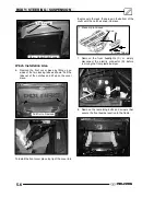
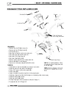
HEADLIGHT POD EXPLODED VIEW
Clean knurling when
repositioning handlebars
*NOTE:
To install handlebars, follow
the handlebar block torque procedure
on the next page.
Disassembly
S
Remove two side Phillips screws (A).
S
Remove one rear Phillips screw (B).
S
Lift top half of pod.
S
Disconnect instrument cluster wire connectors.
S
Disconnect work light switch connector.
S
Disconnect 12V power plug (G).
S
Disconnect headlight harness.
S
Remove ignition switch (C) and choke cable (D).
S
Remove headlight (F) with adjuster.
S
Remove two screws securing bottom half of pod (E).
Assembly
S
Install bottom of pod onto handlebar and secure to brackets.
S
Install key switch, choke cable, and headlight.
S
Connect 12V power outlet (where applicable)
S
Connect headlight.
S
Connect instrument cluster connectors to instrument cluster.
S
Install top of pod onto bottom half, making sure interlocking tabs mate properly.
S
Install two side Phillips screws.
S
Install one rear Phillips screw.
S
To adjust headlight, refer to procedure outlined in Chapter 2.
S
To apply decals, refer to Page 5.20.
E
A
D
C
F
A
B
C
*NOTE:
Refer to Chapter 10 for more
information on headlight pod compo-
nents.
G
Instrument Cluster
Worklight Switch
ETC
Brake
Controls
Wheel Speed Sensor
Содержание Sportsman 800 Efi 2005
Страница 116: ...ENGINE 3 62 NOTES ...
Страница 136: ...FUEL SYSTEM FUEL INJECTION 4 20 NOTES ...
Страница 186: ...CLUTCH 6 30 NOTES ...
Страница 256: ...BRAKES 9 24 NOTES ...
Страница 292: ...ELECTRICAL 10 36 BASIC WINCH WIRING 2005 ATV MODELS 2005 ATV WINCH WIRING DIAGRAM ...
Страница 300: ...ELECTRICAL 10 44 NOTES ...
Страница 301: ...ELECTRICAL 10 39 WIRING DIAGRAM 2005 SPORTSMAN 700 800 EFI Stator ...
Страница 302: ...ELECTRICAL 10 40 WIRING DIAGRAM 2005 SPORTSMAN 700 800 EFI ...


